
Renewable Modelling · Wind Turbine Control

Variable-Speed Wind Turbine Control in EMTP®

Operating regions, cubic MPPT law and pitch control

A variable-speed wind turbine changes its control objective with the wind speed. Below rated wind speed it adjusts the generator torque to maximise aerodynamic capture — maximum-power-point tracking, with a power reference proportional to the cube of the rotor speed. Above rated wind speed it increases the blade pitch to reduce the power coefficient, limiting the mechanical power and protecting the drive train. Below cut-in there is too little wind to generate, and above cut-off the turbine shuts down. What follows sets out the operating regions, the cubic MPPT law, the slow pitch control loop, and why a wind turbine is controlled by torque below rated and by aerodynamics above — nothing like a synchronous generator.

Reading time ≈ 17 min · operating regions, MPPT & pitch control

A variable-speed wind turbine does not draw a fixed power from the wind: it decides how much to take, how fast to turn, and when to stop taking more. A supervisory control makes those decisions by splitting the turbine’s operating envelope into a handful of wind-speed regions, each with one of two objectives — maximise the captured power below rated wind, or limit it above rated wind. The power available in the first place comes from the aerodynamic model; this page is about the control that acts on it, and the slow pitch loop that does the limiting, right through to the electrical control that follows the power reference.

Abbreviations used on this page
WTWind turbine
MPPTMaximum-power-point tracking
\(\beta\)Blade pitch angle
\(\omega_t\)Turbine rotor angular speed
\(\omega_g\)Generator speed
\(P_{ref}\)Power reference
\(K_{opt}\)Optimal-tracking gain
\(\lambda_{opt}\)Optimal tip-speed ratio
\(C_{p,\max}\)Maximum power coefficient
PIProportional–integral controller
RSCRotor-side converter
EMTP®Electromagnetic Transients Program
Key idea
  1. A variable-speed turbine controls itself in regions set by wind speed: off below cut-in; MPPT (maximise power) between cut-in and rated; pitch limiting above rated; shut down above cut-off.
  2. In the MPPT region the pitch is held near its minimum, \(\beta\approx0\), and the power reference follows the cube of the rotor speed, \(P_{ref}=K_{opt}\,\omega_t^3\), which keeps the turbine at the optimal tip-speed ratio and \(C_{p,\max}\).
  3. Above rated wind, the pitch controller increases \(\beta\) to cut the power coefficient and limit the mechanical power, protecting the drive train. The pitch loop is a slow speed-or-power PI regulator driving a mechanical actuator.
  4. A wind turbine is not controlled like a synchronous generator: below rated the wind limits and control maximises capture through torque; above rated the machine limits and control sheds power through aerodynamics. The MPPT power reference then passes to the DFIG rotor-side or Type-4 converter control.
Key terms used on this page
01Supervisory control
The top-level logic that sets the turbine’s operating mode and references by wind region.
02Operating region
A wind-speed band with its own control objective (off, MPPT, pitch-limiting, shutdown).
03Cut-in speed
The wind speed below which the turbine stays shut down (too little energy).
04Rated wind speed
The wind speed at which rated power is reached; above it, pitch limits power.
05Cut-off speed
The wind speed above which the turbine is shut down to avoid overload.
06MPPT region
Between cut-in and rated; \(\beta\approx0\), power reference follows \(\omega_t^3\).
07Cubic power law
\(P_{ref}=K_{opt}\,\omega_t^3\), which holds the optimal tip-speed ratio.
08\(K_{opt}\)
The constant gain set by the turbine design, air density, radius, \(C_{p,\max}\) and \(\lambda_{opt}\).
09Pitch control
Increasing \(\beta\) above rated to reduce \(C_p\) and limit the captured power.
10Pitch actuator
The slow mechanical drive moving the blades; a first-order lag with a rate limit.
11Rate limit
The cap on how fast the pitch angle can change, set by the heavy blades and drive.
12Drive train
The mechanical path from rotor to generator that pitch limiting protects from overload.

Section 1

Supervisory control of the turbine

The control on this page sits above the electrical loops: it decides how much power to produce, how fast to rotate, and when to limit. It does so by recognising which operating region the wind has put the turbine in, and applying the right objective for that region. There are really only two control jobs — extract the most power the wind allows, or hold the power down to protect the machine — and the whole strategy is about knowing which one applies and switching cleanly between them.

Two jobs, by region

Below rated wind speed the objective is to maximise power (MPPT). Above rated wind speed the objective is to limit power (pitch). Everything else is the machinery for choosing between them.

Section 2

The operating regions

The turbine’s behaviour is organised into four regions of wind speed, from too little wind to too much:

Table 1 — The operating regions of a variable-speed wind turbine.
RegionWind SpeedPitch \(\beta\)ControlOutput
Below cut-in\(v < v_{cut\text{-}in}\)Turbine offNo generation
MPPT region\(v_{cut\text{-}in} \le v < v_{rated}\)\(\beta \approx 0\)Speed / torque (MPPT), \(P_{ref}=K_{opt}\omega_t^3\)Maximise power
Above rated\(v_{rated} \le v < v_{cut\text{-}off}\)Increased from minimumPitch limits powerRated power (limited)
Above cut-off\(v \ge v_{cut\text{-}off}\)Turbine shut downNo generation
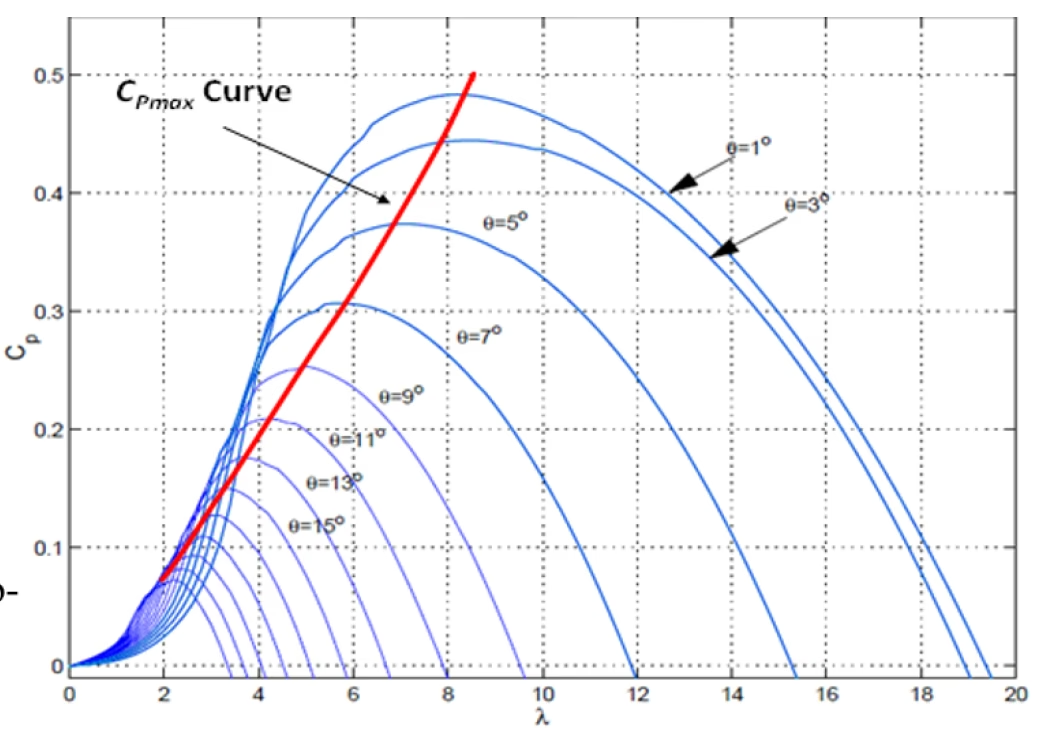
The aerodynamic power coefficient Cp on the vertical axis versus tip-speed ratio lambda on the horizontal axis, drawn as a family of curves for blade-pitch angles theta from 1 to 15 degrees. Each curve peaks and falls, and a red line marks the Cp,max locus joining the peaks; higher pitch angles give lower, left-shifted curves.
Figure 1 — The aerodynamic power coefficient \(C_p\) versus tip-speed ratio \(\lambda\), for a family of blade-pitch angles \(\theta\). Below rated the turbine tracks the \(C_{p,\max}\) locus (red) to extract the most power (the MPPT region); above rated the pitch angle is increased, moving onto lower-\(C_p\) curves to shed aerodynamic power and hold the output at rated.

Section 3

Below rated: maximise power

Between cut-in and rated wind speed sits the most important region. Here the pitch angle is held near zero — its minimum, near-optimum value (\(\beta\approx0\)) — and the power reference for the generator is produced by the maximum-power-point-tracking function so the turbine runs at its best aerodynamic efficiency. In this region the wind, not the machine rating, is the limiting factor, so the controller does not try to hold rated power; it adjusts the rotor speed and generator torque to extract as much of the available wind power as it can. With the pitch fixed, the only free variable is the rotor speed — and choosing it correctly is exactly what keeps the turbine at the peak of its power-coefficient curve.

Section 4

The cubic power reference

MPPT keeps the rotor near the optimum tip-speed ratio, where the power coefficient is highest for the available wind speed. The conventional method then calculates the power reference as a cubic function of the turbine rotor angular speed:

\[ P_{ref} = K_{opt}\,\omega_t^{3}, \qquad K_{opt} = \tfrac{1}{2}\,C_{p,\max}\,\rho\,A\left(\frac{R}{\lambda_{opt}}\right)^{3} \]
\(P_{ref}\)
power reference sent to the generator control
\(\omega_t\)
turbine angular speed
\(K_{opt}\)
optimal-tracking gain (a constant for the turbine)
\(C_{p,\max},\lambda_{opt}\)
maximum power coefficient and the optimal tip-speed ratio
\(\rho,A,R\)
air density, swept area, blade radius

Holding the optimal tip-speed ratio (so \(v=\omega_t R/\lambda_{opt}\) and \(C_p=C_{p,\max}\)) makes the captured power follow \(\omega_t^3\); the gain \(K_{opt}\) is fixed by the turbine design alone — the air density, the blade radius, the maximum power coefficient \(C_{p,\max}\) and the optimal tip-speed ratio \(\lambda_{opt}\). Keeping the rotor speed proportional to the wind speed holds the optimal \(C_p\) and extracts the most energy. This cubic law applies only in the below-rated MPPT region: once the wind exceeds rated the turbine leaves it and pitch control takes over, capping the power at rated.

Section 5

Above rated: pitch to limit power

Above the rated wind speed the problem inverts: there is more energy in the wind than the machine should take, and leaving it uncontrolled would overload the drive train. So the turbine switches to power-limiting mode. The pitch controller increases the pitch angle \(\beta\), which reduces the power coefficient \(C_p\) and therefore the mechanical power extracted from the wind, holding the output near rated and reducing the mechanical loads on the drive train. Pitch control deliberately reduces the aerodynamic efficiency to keep the mechanical power and the drive-train loading within rated limits.

Section 6

Cut-in and cut-off

The two ends of the operating range are simple but important. Below the cut-in speed the wind is too weak for useful energy production, so the turbine remains shut down. Above the cut-off speed the wind is too strong to operate safely even with full pitching, so the turbine is shut down again to protect itself. Between these limits the pitch controller holds the pitch near its minimum for wind speeds below rated, switching to active pitching only once rated wind speed is exceeded.

Section 7

The pitch control loop

The pitch controller itself is a feedback loop. It takes an error — either a speed error or a power error — through a PI regulator, combines the result, and drives the pitch actuator, which is a slow mechanical system modelled as a first-order lag with a rate limit. The two regulating loops are:

Table 2 — The two regulating loops of the pitch controller.
LoopErrorControllerPurpose
Speed loop\(\omega_g - \omega_{ref}\)PIRegulate the turbine / generator speed
Power loop\(P_g - P_{set}\)PIRegulate the generated power
\[ \beta(s) = \frac{K}{1+sT}\,\Delta(s), \qquad \left|\frac{d\beta}{dt}\right| \le \dot{\beta}_{\max} \]
\(\beta\)
commanded pitch angle
\(\Delta\)
combined PI-controller output (from the speed and power loops)
\(K,T\)
pitch-actuator gain and time constant (the first-order lag)
\(\dot{\beta}_{\max}\)
maximum pitch rate (the rate limiter)

The actuator is a slow first-order lag with a rate limit, so the pitch responds gradually rather than instantly — which is exactly the behaviour the heavy blades impose.

Figure 2 — The pitch control loop: a speed PI loop and a power PI loop, combined and driving the pitch actuator (a first-order lag with a rate limit) to set the blade pitch \(\beta\).

Section 8

Why pitch control is slow

The pitch loop is deliberately slow because the thing it moves is slow: the blades are heavy and their mechanical movement takes time. That sets a natural division of labour. Electrical torque and converter current can change quickly, so the electrical control does the fast, moment-to-moment tracking; blade pitch is limited by actuator speed, blade inertia and mechanical loading, so it is used for slower, sustained power limiting. This is not a matter of pitch being a mere backup: below rated wind, electrical torque control performs the fast tracking, and above rated wind, pitch becomes the main aerodynamic power-limiting control. Forcing the pitch to move fast would fight the actuator and stress the mechanism, so it is left to the job it suits — the gradual, sustained reduction of aerodynamic capture above rated wind.

Section 9

The control philosophy

Stepping back, the strategy is a clean two-mode philosophy. Below rated wind, the pitch is held near zero and the turbine follows the cubic MPPT law through speed and torque control, maximising the energy captured. Above rated wind, the pitch is increased to reduce the aerodynamic power and protect the turbine. Each mode has one job, and the boundary between them is the rated wind speed.

Below vs above rated

Below rated: \(\beta\approx0\), MPPT, maximise capture (fast torque control). Above rated: increase \(\beta\), reduce \(C_p\), limit power (slow pitch control). One boundary, two objectives.

Section 10

Not controlled like a synchronous generator

A variable-speed wind turbine is not controlled like a synchronous generator, where the mechanical input sets the power directly. It has two limiting factors in two regimes: below rated wind the wind limits, so the control maximises extraction by adjusting torque (MPPT); above rated wind the machine limits, so the control limits extraction by adjusting aerodynamics (pitch). The control variable changes with the regime — which is what makes wind control distinctive.

Section 11

Link to the electrical control

This supervisory control is where the turbine’s active-power reference is born, and it closes the loop with everything on the electrical side. The supervisory wind-turbine controller produces the active-power reference \(P_{ref}\) from MPPT; that reference is passed to the generator control — the rotor-side converter in a DFIG, or the machine-side converter in a Type-4 turbine — which turns it into the current or torque commands the inner loops track. So when a later study shows a converter following a power reference, that reference traces all the way back here: through MPPT, to the best operating point, to the turbine aerodynamics.

Section 12

Key points

Maximise below rated, limit above — by torque then pitch

  1. Below rated wind speed the turbine runs MPPT, adjusting generator torque and rotor speed to extract as much of the available wind power as possible.

  2. In that region the power reference follows the cubic law \(P_{ref}=K_{opt}\,\omega_t^3\), which holds the optimal tip-speed ratio and \(C_{p,\max}\); it applies only below rated wind.

  3. Above rated wind speed the turbine pitches the blades to reduce \(C_p\) and limit the mechanical power, protecting the drive train.

  4. Pitch is slower than electrical torque and converter-current control: the blades are heavy, so torque does the fast tracking and pitch the sustained limiting.

  5. The supervisory MPPT power reference is passed to the converter control — the DFIG rotor-side or Type-4 machine-side converter — which turns it into current or torque commands.

For the source behind the reference, see the wind turbine aerodynamics guide; for the wider plant, the wind-park modelling and full-scale converter control guides.

References

References

  1. EMTP® Documentation and Application Notes. Powersys / EMTP®.
Built on EMTP® · Expert spotlight
Portrait of Henry Gras, Chief Operating Officer of PGSTech

Henry Gras

Chief Operating Officer, PGSTech · Montréal, Canada

Henry Gras delivers the EMTP® University course “EMT Simulation and Analysis of Large-Scale Power Systems with Renewables” and works daily with the tool this article is written around.

Henry is based in Montréal, where he is Chief Operating Officer of PGSTech, the company responsible for EMTP® engineering services, commercialisation and continuing software development. He holds a master’s degree from Polytechnique Montréal, where he worked on electrical-machine research, and previously completed an engineering degree at École Centrale de Lyon in France.

Readers who want a structured programme on EMT simulation of large-scale power systems with renewables will find his EMTP® University course an excellent next step.

Henry’s technical expertise covers electromagnetic transient simulation, renewable-energy integration, power-system modelling, electrical machines, protection and specialist transient studies including TRV, transformer energisation, ferroresonance, insulation coordination and power quality.

Thirty-Part Technical Series

EMTP® Renewable Energy Modelling

A thirty-part guide to modelling wind, PV and full-converter plant in EMTP® — sources and turbines, converter and plant control, sequence control under faults, protection, and weak-grid and SSCI stability.

Part 24 Reading now

Variable-Speed Wind Turbine Control: MPPT and Pitch

Operating regions, the cubic MPPT law below rated, and pitch control above rated wind speed.

Series progress 24 of 30

