
Renewable Modelling · White-Box & Black-Box Models

White-Box and Black-Box Renewable Models in EMTP®

Plant physics, controller transparency and OEM DLL models

When a manufacturer supplies a wind or PV plant model, the electrical plant — machine, converters, dc link, transformer and the connection to the grid — is usually built from familiar EMT components, and that part is common to every model. What changes is the control block. In a white-box model the control is open: the PLL, the loops, the FRT logic and the limiter priorities can be inspected, and in EMTP®’s generic models modified. In a black-box model the control is a compiled OEM implementation: its inputs and outputs are available, but the internal logic is hidden. Understanding the boundary between the visible electrical plant model and the hidden controller implementation is essential for model selection, validation and interpretation of EMT study results.

Reading time ≈ 18 min · controller transparency, DLL models & OEM practice

A renewable plant model always contains two very different parts: the electrical plant and the controller. The electrical plant — the machine, the converter hardware, the dc link and the transformer — is usually modelled in a fairly standard way from EMT components. The controller can come in one of two forms, white box or black box: the difference is not whether a transformer or a dc link exists, but whether the control structure inside can be seen and understood. The distinction between white-box and black-box modelling determines what can be inspected, tuned, validated and diagnosed during an EMT study.

Abbreviations used on this page
OEMOriginal equipment manufacturer (the vendor)
DLLDynamic-link library (compiled code)
EMTElectromagnetic transient (simulation)
AVMAverage-value model (no switching detail)
PMSGPermanent-magnet synchronous generator
DFIGDoubly-fed induction generator
PCCPoint of common coupling
PLLPhase-locked loop
FRTFault ride-through
SSCISub-synchronous control interaction
IPIntellectual property
EMTP®Electromagnetic Transients Program
Key idea
  1. There are two kinds of renewable model, and the difference is in the control, not the plant. The electrical part — machine, converters, dc link, transformer and the connection to the PCC — is usually built from the same standard EMT components in both.
  2. A white-box model exposes the control structure — the PLL, the dq loops, the FRT logic, the limiter priorities, the sequence control — so you can inspect it, ask precise questions, and in EMTP®’s generic models even modify it.
  3. A black-box model hides the control inside a compiled DLL — an OEM controller implementation meant to reproduce the real plant controller’s behaviour. An interface feeds it measurements and references and reads back gate signals, voltage references and flags; the behaviour can be close to the real plant, but the internal logic is concealed and the model still needs validation.
  4. Black box is not bad, just less transparent. The real risk is diagnostic: if it gives a result you do not like, you may not be able to see why. Technical literacy lets you ask the right questions of either model.
Key terms used on this page
01White-box model
A model whose control structure is visible and can be inspected and, in generic models, modified.
02Black-box model
A model whose control behaviour is available through its interfaces while the internal logic is hidden.
03DLL
A dynamic-link library holding the compiled controller code, called by the simulation through an interface.
04Interface
The bridge that feeds the DLL with simulation quantities and returns its outputs to the network model.
05OEM compiled controller
The black-box DLL: the manufacturer’s controller implementation, compiled to reproduce the plant controller’s behaviour while protecting its logic.
06Time-mesh interpolation
Aligning DLL inputs and outputs to the simulation time-step when the DLL runs at its own rate.
07Average-value model
A converter model that omits switching detail; may be unavailable in some black-box models.
08Flat start
Initialising the simulation directly from load-flow results; often hard for black-box models.
09Intellectual property
The proprietary control logic vendors protect by supplying a black box rather than open code.
10Commissioning
Site bring-up; firmware changed afterwards can leave a delivered black box out of date.
11Model validation
Benchmarking the model against measured or specified response so its behaviour can be trusted.
12Controller transparency
The degree to which the model lets you see and reason about the control — the whole white/black distinction.

Section 1

Two kinds of model

There are two types of renewable model in circulation: white box and black box. The difference between them is mainly in how the controls are modelled — the rest of the model, the electrical components, is common to both. It is worth stating this plainly, because the names can suggest a bigger difference than there is. A black-box model is not a different plant; it is the same plant with a different kind of control block. So the real question a white-box-versus-black-box choice answers is simple: can you see and understand the internal controller structure, or not?

The question to ask

When a model arrives, the first useful question is not “does it have a dc link?” but “is the control white box or black box, and what exactly is exposed?” Everything else follows from that.

Section 2

What stays common: the electrical plant

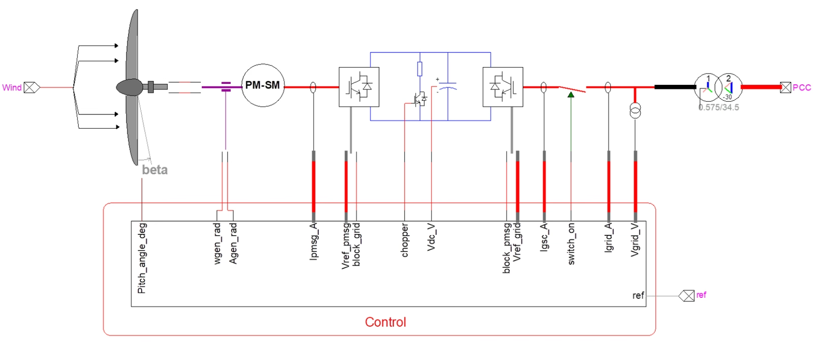
In both model types the physical plant is generally still there and still recognisable: the aerodynamic and mechanical wind input, the machine (a PMSG or a DFIG, for example), the converter hardware, the dc link, the grid transformer, the connection to the point of common coupling, and the current, voltage, dc-link and switching interfaces around them. The electrical skeleton is built from the same standard EMT components either way. What is enclosed as the Control block is the part that changes — it may be your open generic control, the manufacturer’s white-box control, or a black-box replacement.

Full-converter wind-turbine plant in EMTP: the wind input and pitched turbine blades drive a PM-SM machine, feeding a machine-side converter, a dc link with chopper and capacitor, a grid-side converter, a switch and a 0.575/34.5 kV transformer to the PCC; below sits a separated Control block that takes all the plant measurements and references and returns the control outputs. The electrical plant is common to both model types, while the Control block is the part that may be white box or black box.
Figure 1 — The whole plant still exists in both model types — wind input, machine, converters, dc link, transformer and the connection to the PCC. The separated Control block is the part that may be your open generic control, an OEM white-box control, or a black-box replacement.

Section 3

What a white-box model means

A white-box model is one whose control structure is visible and understandable. You can go inside and see the building blocks: the PLL, the dq transformations, the outer voltage loop, the inner current controllers, the FRT logic, the current limiter, the pitch control, the protective blocks, the measurement filters and the sequence control. In other words, the control is transparent enough that you can inspect what signals are measured, what blocks and equations are used, what references are generated, and how the limits and priorities are implemented. White box means the inside is visible — not necessarily simple, but visible.

Section 4

Why white-box models are valuable

A visible control lets you do the things that matter in difficult studies: understand the real control philosophy, trace why a converter responds the way it does, modify parameters or even structure, benchmark behaviour, identify possible causes of instability, relate the control blocks to the converter’s impedance behaviour, and carry out genuine research. It also lets you ask meaningful, specific questions instead of accepting a vendor’s claim at face value:

  • Where is the PLL, and how fast is it tuned?
  • What current priority is used during FRT — active or reactive current first?
  • Is there negative-sequence control, and is it enabled?
  • What measurement-filter type and cut-off are used?
  • What are the limiter priorities, and how are limits implemented?
  • How is the dc-link control tuned, and is the controller coupled or decoupled?

Those are white-box questions: they can only be answered if the control can be seen inside. Transparency, though, is not the same as accuracy — a visible control still has to be validated against the manufacturer’s specified or measured response before its results can be trusted.

Section 5

What a black-box model means

A black-box model is one whose control block is not visible in the same detailed way. You may still know its inputs, its outputs and some parameters, but you do not see the internal logic explicitly. From the outside it behaves like a sealed unit: give it measurements and references, and it gives back converter commands or a plant response — while the internal controller equations and structure stay hidden. Black box means the behaviour is available, but the control logic is concealed.

Table 1 — White-box and black-box models at a glance.
AspectWhite BoxBlack Box
Electrical plantStandard EMT componentsStandard EMT components (the same)
Control structureVisible — blocks and signals exposedHidden — compiled DLL, interfaces only
Inspect / modifyYes; parameters and often structureNo; inputs, outputs and some parameters only
Fidelity comes fromThe modelled control blocks (need validation)The OEM controller implementation (needs validation)
IP exposureOpen control logicProtected — logic not disclosed
InitialisationUsually straightforward; flat start feasibleOften hard; may need seconds of run-up
Best forWeak-grid, PLL, sequence and research workCompliance and benchmarked-response studies

Section 6

How a black box works: the DLL and the interface

In a black-box model the control is supplied as compiled code in a dynamic-link library (DLL). The DLL is the manufacturer’s controller implementation, built to reproduce the behaviour of the real product while keeping its internal logic private. An interface sits between the DLL and the network model. At each call, EMTP® sends the DLL the simulation time, the measured voltages and currents, the power references and status signals. The DLL returns its outputs — voltage references, gate signals, current commands or protection flags. Those outputs are then applied back to the network model.

One detail matters for accuracy. The DLL often runs at its own fixed sampling rate, which need not match the simulation time-step. When the DLL’s call instants do not fall on the simulation time-mesh, its inputs and outputs have to be interpolated or aligned in time:

\[ u_{\mathrm{DLL}}(t_k) = u_{\mathrm{sim}}(t_k), \qquad y_{\mathrm{sim}}(t) \approx y_k + \frac{y_{k+1}-y_k}{T_s}\,(t - t_k), \quad t_k \le t < t_{k+1} \]
\(T_s\)
the DLL sampling period (its own operating rate)
\(t_k = k\,T_s\)
the instants at which the DLL is actually called
\(u_{\mathrm{DLL}}\)
inputs handed to the DLL (currents, voltages, references)
\(y_k\)
the DLL output sampled at \(t_k\) (gate signals, voltage references, flags)
\(y_{\mathrm{sim}}(t)\)
the output mapped onto the simulation time-mesh between calls

When the simulation time-step does not match the DLL rate \(T_s\), the interface interpolates so the DLL’s inputs and outputs land on the simulation time-mesh. If this sampling, interpolation or time-step is not handled correctly, the response can pick up numerical delay, aliasing or plainly incorrect transient behaviour — which is why some black-box models impose their own time-step restrictions.

Section 7

Why manufacturers prefer black-box models

Manufacturers often prefer black-box models for a straightforward reason: the control system is intellectual property. It contains proprietary logic, special tuning, vendor-specific know-how and protection strategies they do not want to disclose. From their point of view, releasing the open control architecture means giving away the product. So they are typically comfortable sharing the electrical topology, the interface points and perhaps a compiled model — but not the open control. That is why black-box models are common in real projects, and why a delivered model so often pairs a familiar electrical skeleton with a sealed control block.

Section 8

Black-box advantages

A black box is not a poor relation. Built from the real control code, it has real strengths:

  • Close to OEM behaviour. Built from the manufacturer’s own controller implementation, a validated black box can reproduce the supplied plant controller closely.
  • Fast to simulate. Compiled code typically runs quickly, which helps in large or long studies.
  • Solves the disclosure problem. The vendor can share behaviour without exposing source code, so the intellectual-property and non-disclosure obstacle is removed.
  • Reusable across tools. The same compiled model can often be used with different EMT programs.

Section 9

Black-box drawbacks

The same concealment that protects the vendor’s code is what makes a black box harder to live with as an engineer:

Practical limitations of black-box models
  • It is hard for the end user to understand and investigate unexpected behaviours, and hard to notice or detect model design flaws.
  • Only a limited number of signals are available to visualise.
  • Some black-box models impose time-step restrictions because of their sampling method.
  • Initialisation is difficult because the controller’s internal states are hidden. If those states are not consistent with the load-flow operating point, a flat start is hard to achieve: the model can show an artificial start-up transient, or need several seconds of simulation to settle before the real disturbance is applied.
  • The model is typically provided before commissioning; if the converter firmware is updated afterwards and the black-box code is not, the model can become obsolete.
  • Functions specific to real-time operation may stop the model running properly offline, and time-step integration error may force a very small time-step.
  • It may require the end user to install a compiler, and it may not allow an average-value model if the voltage references are not available.

Section 10

When things go wrong

A black-box model can still be very useful, but it becomes awkward exactly when you most need insight: when results look strange, when the plant becomes unstable, when the model will not initialise, when the response does not match measurements, or when you are trying to understand a weak-grid issue, assess SSCI or PLL-related behaviour, and explain it to the TSO or the client. In those moments you cannot easily ask which loop caused it, which limiter was active, whether the PLL is too fast, whether negative-sequence control is enabled, or whether the filter or priority logic is responsible. You see the result, but not the mechanism — and that is the central engineering limitation of a black box.

Section 11

Generic models versus OEM models

The generic wind and PV models are much closer to the white-box style: you can inspect the controller, see the structure, change parameters and, in many cases, modify the architecture itself. The internal control is open. When a manufacturer model arrives, the electrical skeleton may still look familiar — the same recognisable machine, converters, dc link and transformer — while the control block becomes an OEM architecture that is either open enough to inspect or closed as a black box. The platform is acting as the host either way; the degree of transparency depends on who supplied the model, not on the simulator.

This is also why generic white-box models exist as a category rather than being a fallback for when no OEM model is available. A manufacturer model may be highly accurate, but it arrives as a black box under a non-disclosure agreement, so its internal control cannot be examined. Utilities and developers therefore need an accurate generic model of their own for the preliminary interconnection studies carried out before a specific machine and its OEM model are committed to, and researchers need one to explore integration issues — weak-grid interaction, sequence behaviour and control tuning — that a sealed OEM model simply will not let them open up. A good generic model is not a rough stand-in; it is the transparent counterpart that makes those early and investigative studies possible.

Section 12

When each kind fits

A white-box model is especially valuable when the study itself depends on understanding the inside of the control: weak-grid stability, PLL behaviour, sequence control, benchmarking FRT logic, tuning plant controls, deriving impedance behaviour from the controller, research, and explaining why one plant is stable and another is not. A black-box model, by contrast, is acceptable when the goal is project-level compliance checking, standard EMT performance studies, reproducing a benchmarked OEM response, or validating the response to a defined disturbance set — provided the model has been validated, initialisation works, the interfaces are clear and the behaviour is trustworthy.

Rule of thumb

Use white-box models when the study needs visibility into PLL behaviour, sequence control, limiter priority, weak-grid interaction or controller modification. Use validated black-box models when the objective is compliance, OEM benchmark reproduction or behaviour close to the supplied plant controller. Black box does not mean bad — it means less transparent.

Section 13

The real engineering risk

The biggest risk of a black box is not that the model is hidden — it is that if the model gives a result you do not like, you may not know why. At that point you become dependent on the manufacturer to explain which block acted, whether the result is physical, whether some hidden limiter or protection triggered, and whether the model is being used outside its valid range. That dependence is exactly why technical understanding matters. You do not need to redesign the vendor’s converter, but you should know enough to ask the right questions — is this white box or black box, what is exposed, what protection logic is included, what operating modes are represented, is it average-value or switching, is FRT implemented, what PLL type is used, and what are its limitations.

Why the literacy matters

Understanding the converter structure, the PLL, sequence control and FRT is what lets an engineer interrogate a delivered model on its merits — asking precise questions about its controller, its operating modes and its valid range, rather than accepting its output at face value.

Section 14

Key points

Same plant, different controller transparency

  1. Common electrical plant. White-box and black-box models usually share the same electrical plant — machine, converters, dc link, transformer and the connection to the PCC, built from standard EMT components.

  2. Controller transparency. The real difference is whether the controller is open and inspectable (white box) or compiled and hidden (black box); a black box exchanges signals through a DLL interface that interpolates onto the simulation time-mesh.

  3. White-box strengths. Transparent and diagnosable, well suited to PLL, sequence-control, weak-grid and SSCI studies — but transparency is not accuracy, so it still needs validation.

  4. Black-box strengths and limits. Close to OEM behaviour and protects intellectual property, but harder to inspect, initialise and diagnose, with possible time-step restrictions and obsolescence.

  5. Selection and validation. Choose white box when the study needs to understand the control, a validated black box for compliance and benchmarked-response work — and validate either way.

References

References

  1. EMTP® Documentation and Application Notes. Powersys / EMTP®.
Built on EMTP® · Expert spotlight
Portrait of Henry Gras, Chief Operating Officer of PGSTech

Henry Gras

Chief Operating Officer, PGSTech · Montréal, Canada

Henry Gras delivers the EMTP® University course “EMT Simulation and Analysis of Large-Scale Power Systems with Renewables” and works daily with the tool this article is written around.

Henry is based in Montréal, where he is Chief Operating Officer of PGSTech, the company responsible for EMTP® engineering services, commercialisation and continuing software development. He holds a master’s degree from Polytechnique Montréal, where he worked on electrical-machine research, and previously completed an engineering degree at École Centrale de Lyon in France.

Readers who want a structured programme on EMT simulation of large-scale power systems with renewables will find his EMTP® University course an excellent next step.

Henry’s technical expertise covers electromagnetic transient simulation, renewable-energy integration, power-system modelling, electrical machines, protection and specialist transient studies including TRV, transformer energisation, ferroresonance, insulation coordination and power quality.

Thirty-Part Technical Series

EMTP® Renewable Energy Modelling

A thirty-part guide to modelling wind, PV and full-converter plant in EMTP® — sources and turbines, converter and plant control, sequence control under faults, protection, and weak-grid and SSCI stability.

Part 17 Reading now

White-Box and Black-Box Renewable Models

Visible generic models and OEM compiled models — what controller transparency changes in EMT studies.

Series progress 17 of 30

