
Renewable Modelling · EMT versus RMS

EMT versus RMS for Weak-Grid Converter Instability in EMTP®

SCR, grid-side converter current loop and PLL dynamics

Weak-grid converter instability is often governed by fast converter-control dynamics that are not fully represented in RMS transient-stability models. EMT simulation is required when the interaction between the grid-side converter current loop, the PLL and the weak network impedance determines the response. The case here is a three-phase fault cleared after 200 ms by isolating the faulted line, which sharply drops the short-circuit ratio (SCR) at a wind plant’s point of interconnection. In the RMS transient-stability program the post-fault system looks stable; in the EMT model it develops a growing oscillation — because the RMS model does not represent the fast grid-side converter current loop and PLL dynamics that dominate here. What follows sets out SCR, why clearing weakens the grid, and why those fast loops decide the answer.

Reading time ≈ 18 min · SCR, weak grid & why EMT is needed

Most of this series has been about how to model renewable plants in EMT. The prior question is why EMT at all, and not the faster RMS transient-stability tool that planners often reach for first. An RMS (root-mean-square) or transient-stability program (TSP) uses a positive-sequence phasor representation aimed at slower electromechanical dynamics; an EMT (electromagnetic-transient) model uses an instantaneous three-phase representation that also includes the fast controls and network transients. In a weak-grid post-fault case, the RMS model can report a stable system while the EMT model shows a growing oscillation. RMS is not generally unreliable — it is well suited to electromechanical stability — but it can miss a fast converter-control instability when the deciding dynamics are outside its bandwidth or not represented. Understanding why comes down to two fast control loops that a simplified RMS model leaves out.
Abbreviations used on this page
EMTElectromagnetic transient (simulation)
RMSRoot-mean-square (phasor) simulation
TSPTransient-stability program
SCRShort-circuit ratio (grid strength)
POIPoint of interconnection
GSCGrid-side converter
PLLPhase-locked loop
WPWind plant
\(S_{sc}\)Short-circuit power
\(Z_{th}\)Thévenin grid impedance
IBRInverter-based resource
EMTP®Electromagnetic Transients Program
Key idea
  1. In a weak-grid post-fault case the RMS / transient-stability model can look stable while the EMT model goes unstable. The danger is often not the fault but the post-fault topology, which lowers the short-circuit ratio at the plant’s point of interconnection.
  2. A low SCR means a weak grid: the terminal voltage is soft, so the converter and the network interact strongly, and the PLL and current-control dynamics become decisive.
  3. The RMS tool misses the instability because it disregards the GSC inner current loop and the PLL dynamics. EMT represents them explicitly, along with the instantaneous three-phase behaviour, so the weak-grid interaction appears.
  4. This is a fast converter-control / weak-grid problem, not a classical rotor-angle one. When SCR is low and the converter dominates — suspected current-loop or PLL-driven oscillation — EMT is necessary.
Key terms used on this page
01EMT simulation
Instantaneous three-phase simulation that captures fast electromagnetic and control dynamics.
02RMS / TSP
Positive-sequence phasor transient-stability simulation, focused on slower electromechanical dynamics.
03Short-circuit ratio
The ratio of grid short-circuit power to plant rating; a measure of grid strength.
04Weak grid
A low-SCR network with a soft terminal voltage and strong converter–network interaction.
05Point of interconnection
The bus where the plant connects to the grid; where the SCR and stability are assessed.
06Inner current loop
The fast GSC control that forces currents to track references; shapes the converter impedance.
07PLL dynamics
The angle-tracking loop’s behaviour; in a weak grid it interacts with the terminal voltage.
08Negative damping
The condition where the control feeds energy into an oscillation, making it grow.
09Post-fault topology
The network left after a fault is cleared; here, weaker because a line is removed.
10Rotor-angle stability
Classical electromechanical stability of synchronous machines — what TSP was built around.
11Inverter-based resource
A converter-interfaced plant (wind, PV, BESS) whose dynamics differ from a synchronous machine.
12Thévenin impedance
The equivalent grid impedance at the POI; larger when a line is removed.

Section 1

Why EMT rather than RMS

The point is practical: in this weak-grid case, the RMS transient-stability model reports a stable system, while the EMT model shows it becoming unstable. That is not a modelling nicety — it is the difference between signing off a connection that is fine and one that will oscillate. The RMS model is not wrong in general; it is well suited to electromechanical stability, but here the deciding dynamics sit in the converter’s fast control, outside what the RMS model represents. The rest of this page is about why the two tools disagree, and why EMT is the one to trust for this class of problem.

Two tools, different bandwidths

RMS sees the plant as a simplified positive-sequence device and reports stability; EMT sees it as a real converter with fast control and reports the oscillation. In a weak grid, where those fast loops dominate, that difference is decisive — and EMT is the tool to trust for this class of problem.

Section 2

The weak-grid scenario

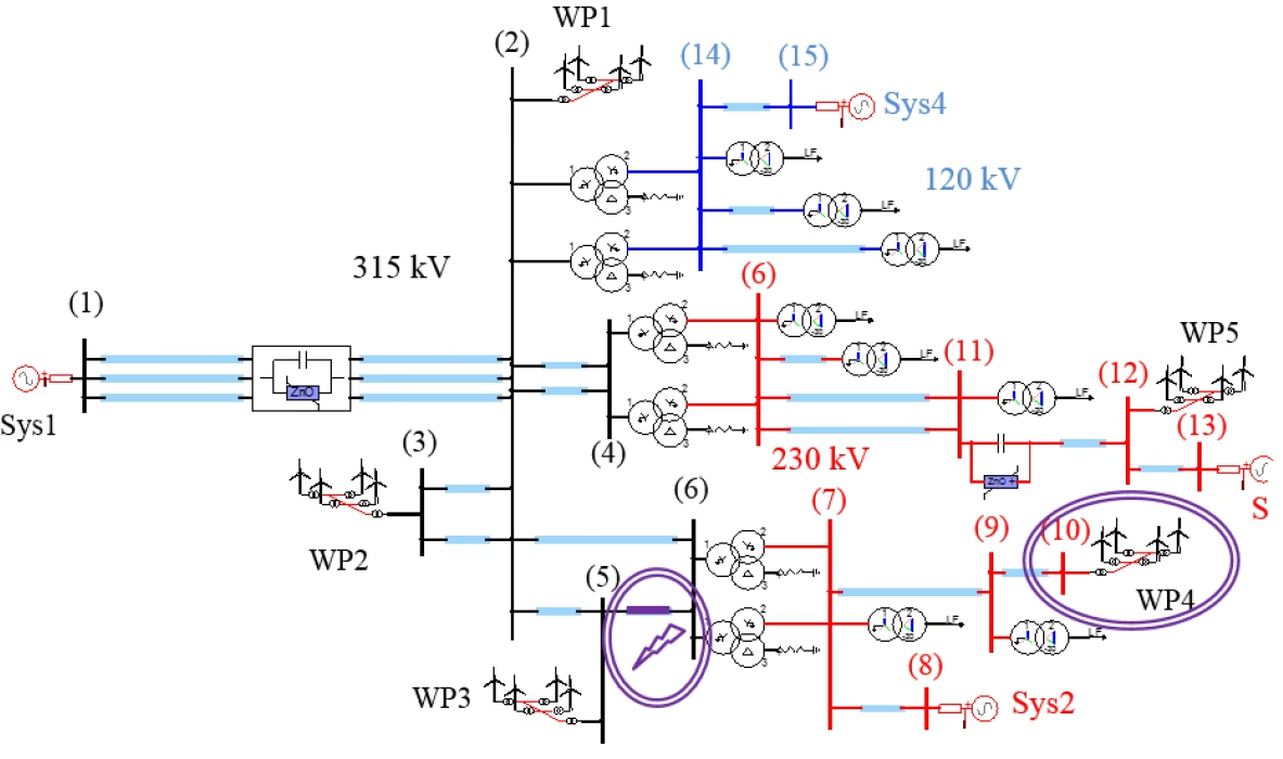
The case is specific. A three-phase metallic fault occurs at the Bus-6 end of the Bus-5 to Bus-6 line, and is cleared after 200 ms by isolating the faulted line. Removing that line is the crux: it significantly reduces the short-circuit ratio at the point of interconnection of wind plant WP4, and the post-fault system then becomes unstable. So this is not simply a fault study — it is a post-fault weak-grid instability study, where the dangerous condition is the topology left behind, not the fault itself.

Single-line diagram of the multi-bus study network: a Sys1 source and a series-compensated 315 kV network, a 230 kV network with Sys2 and a further source, and a 120 kV network with Sys4, feeding five wind parks WP1 to WP5 through step-up transformers, with buses numbered 1 to 15. A three-phase fault is marked on the line between Bus 5 and Bus 6, and WP4 near buses 9 and 10 is highlighted as the point of interconnection whose short-circuit ratio collapses once that line is isolated.
Figure 1 — The scenario: a three-phase fault on the Bus-5 to Bus-6 line, cleared in 200 ms by isolating that line, which sharply lowers the short-circuit ratio at the POI of WP4 — the post-fault weak-grid condition under study.

Section 3

Short-circuit ratio and grid strength

The short-circuit ratio is a measure of grid strength seen by the converter — the ratio of the grid’s short-circuit power at the point of interconnection to the plant’s rating:

\[ \mathrm{SCR} = \frac{S_{sc}}{P_n}, \qquad S_{sc} = \frac{V_n^2}{\lvert Z_{th}\rvert} \]
\(\mathrm{SCR}\)
short-circuit ratio at the point of interconnection
\(S_{sc}\)
grid short-circuit power at that point
\(P_n\)
plant rated power
\(V_n,\lvert Z_{th}\rvert\)
nominal voltage and Thévenin grid-impedance magnitude

A high SCR is a strong grid: the terminal voltage is stiff, so the converter has a firm reference and control is easy. A low SCR is a weak grid (commonly taken as SCR below about 3, very weak below 2): the converter current has a stronger effect on the terminal-voltage magnitude and angle, so the PLL and current-control dynamics matter far more.

A screening indicator, not the whole story

SCR is a useful first measure of grid strength, but weak-grid behaviour also depends on the X/R ratio and impedance angle, the converter control mode, the PLL settings, the current limits and any nearby reactive equipment. Treat SCR as a screening indicator, not a complete stability assessment.

Section 4

Why clearing the line weakens the grid

Isolating the faulted line removes one of the parallel paths feeding the point of interconnection, which raises the Thévenin impedance seen there. A larger impedance means less short-circuit power, and so a lower short-circuit ratio:

\[ \text{line removed} \ \Rightarrow\ \lvert Z_{th}\rvert \uparrow \ \Rightarrow\ S_{sc} \downarrow \ \Rightarrow\ \mathrm{SCR}_{post} \lt \mathrm{SCR}_{pre} \]
\(\mathrm{SCR}_{pre},\mathrm{SCR}_{post}\)
short-circuit ratio before and after clearing
\(\lvert Z_{th}\rvert\uparrow\)
the Thévenin impedance rises when a line is removed

The sequence is: fault → line isolation → higher Thévenin impedance → lower SCR → softer terminal-voltage reference → stronger converter–grid interaction. So WP4 ends the event in a low-SCR, weak-grid environment it was not in before, and the instability appears after clearing because that is when the grid becomes weak — a topology-dependent, post-fault weak-grid instability.

Section 5

What the comparison shows

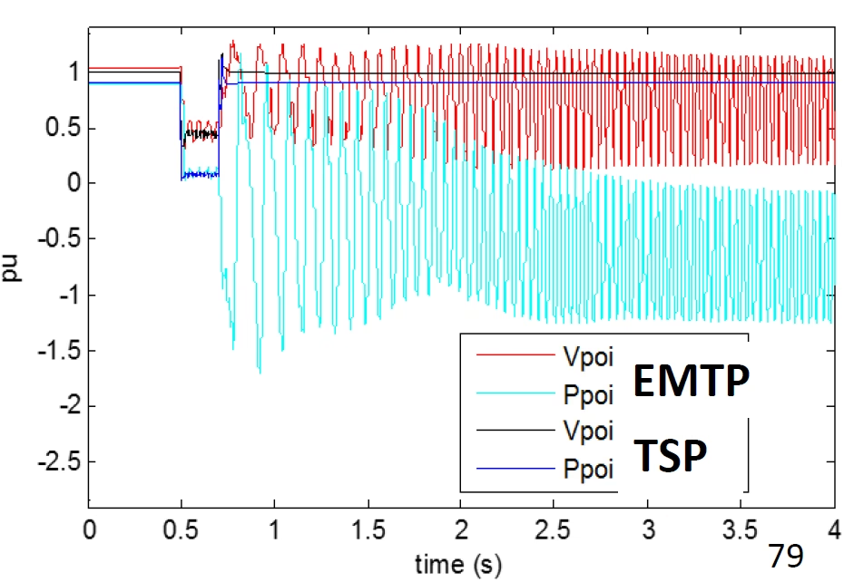
The two tools are run on the same event and the point-of-interconnection voltage and active power compared. The RMS / transient-stability traces are relatively well behaved: the voltage recovers and the power response looks acceptable, so on that evidence the system seems stable enough. The EMT traces tell a different story — a growing oscillation in the POI voltage and active power. Importantly, that oscillation is not the fault response itself: it develops after clearing, once the post-fault weak-grid topology is established, so it is a post-fault instability rather than a fault-ride-through failure. Same disturbance, same network, opposite conclusions.

Plot of point-of-interconnection voltage and active power in per unit versus time for the same fault event, from two tools. The TSP (RMS transient-stability) traces — Vpoi in black and Ppoi in blue — recover after the fault clears near 0.7 s and stay flat and stable. The EMTP (electromagnetic transient) traces — Vpoi in red and Ppoi in cyan — instead break into a large, growing oscillation, the active power swinging between about +1 and -1.5 pu, revealing an instability the RMS tool misses.
Figure 2 — The same event, two tools. Notice that the RMS / transient-stability traces recover and look stable, while the EMT traces develop a growing oscillation in the POI voltage and active power after clearing — the difference comes from the fast converter-control dynamics (the GSC current loop and PLL) that the RMS model omits.

Section 6

Why the two tools differ

The reason is specific to this representation: in this case the RMS transient-stability model does not include the fast grid-side converter current loop and the detailed PLL dynamics that dominate the observed instability, so it does not reproduce it. Those are exactly the parts that become dominant in weak-grid instability. If a model neglects or oversimplifies them, it can miss the problem — which is precisely what happens here.

The decisive sentence

RMS/TSP misses the instability by leaving out the GSC inner current loop and the PLL dynamics — the fast loops that drive weak-grid converter instability. EMT keeps them, so it sees the oscillation.

Section 7

What RMS models, and what it omits

A transient-stability package models the network’s electromechanical dynamics, the slower control loops and the positive-sequence behaviour very well, which is ideal for RMS voltage and angle behaviour, slower system-level stability and many planning studies. What it does not represent in enough detail are the fast converter controls. The contrast is stark:

Table 1 — What RMS / TSP and EMT each represent.
AspectRMS / TSPEMT (EMTP®)
Time resolutionElectromechanical (slower)Electromagnetic (fast)
Phase representationPositive-sequence phasorInstantaneous three-phase
GSC inner current loopSimplified or neglectedExplicit
PLL dynamicsSimplified or neglectedExplicit
Unbalance / asymmetryPositive-sequence onlyFull three-phase, unbalanced faults
Protection / switching detailCoarseDetailed
Study speedFast, large systemsSlower, smaller scope
Best applicationPlanning, rotor-angle stabilityFast converter–grid interaction, weak grids
Main limitationMisses fast converter-control modesComputational cost and scope

Section 8

Why the inner current loop matters

The GSC inner current loop is the fast electrical actuator of the converter. It sets how quickly the converter reacts to a voltage disturbance, how dq current errors are corrected, how the converter behaves against a weak terminal voltage, and — crucially — what effective impedance the converter presents to the grid. In a strong grid this is less troublesome, because the network voltage is stiff and absorbs the converter’s actions. In a weak grid the converter and the network push hard on each other, so the fast current loop becomes part of the instability mechanism itself. That is why EMT, which models the loop, sees the issue, and RMS, which does not, may not.

Section 9

Why the PLL matters

The PLL is often the single most important instability driver in weak grids. It estimates the terminal-voltage angle, but in a weak grid the converter current also changes that terminal voltage, so the PLL is not a passive measurement block: it is interacting with the grid. This creates a feedback path between the converter current injection, the terminal-voltage angle and the controller response. That interaction can create phase errors, dq coupling, negative damping (the control feeding energy into the oscillation rather than dissipating it) and oscillatory modes — the very mechanism behind this instability. A simplified RMS model usually does not represent it with enough fidelity, so the instability is invisible there and obvious in EMT.

The instability mechanism, step by step

In a weak grid: the converter current changes the terminal voltage → the PLL-estimated angle is disturbed → the dq current commands become misaligned → the converter injects current with poor phase and damping → the oscillation grows. Each step feeds the next, which is why the fast loops, not the fault, decide the outcome.

Section 10

Not a rotor-angle problem

The deeper point is that this instability is not a classical synchronous-machine, rotor-angle phenomenon — it is a fast converter-control / weak-grid interaction. The transient-stability tool was built around the electromechanical mechanisms of synchronous machines; this instability lives in the converter’s current loop and PLL. The difference between a strong and a weak grid is what brings it out:

Table 2 — How the converter behaves in a strong versus a weak grid.
AspectStrong Grid (High SCR)Weak Grid (Low SCR)
Terminal voltageStiff — a firm referenceSoft — moves with converter current
Converter–grid interactionWeakStrong — they push on each other
PLLTracks cleanlyInteracts with the grid; can destabilise
Inner current loopWell behavedPart of the instability mechanism
Tool neededRMS often adequateEMT necessary

Section 11

When RMS is enough, and when you need EMT

This case marks the boundary between “RMS is enough” and “you need EMT”. It shows why RMS results should be treated cautiously when fast converter controls are likely to dominate the response — not that RMS is unreliable in general. EMT is the appropriate tool when the study involves:

  • A low short-circuit ratio — a weak grid at the point of interconnection — with grid-following converters.
  • Suspected PLL-driven or inner current-loop oscillation, or converter dominance with few synchronous machines nearby.
  • SSCI or subsynchronous modes.
  • Unbalanced faults or detailed fault-ride-through (FRT) behaviour.
  • Protection and control interactions, or grid-forming / grid-following converter interaction and PLL-sensitivity studies.

RMS, by contrast, may still be perfectly adequate where fast converter controls are not the determining factor:

  • Wider-area electromechanical dynamics and rotor-angle stability.
  • Slower voltage recovery and reactive-support studies.
  • Dispatch, load-flow-driven and planning studies.
  • System frequency response and inertia studies.
  • Broad screening, before a targeted EMT study on the flagged cases.

When the response is decided by the converter’s fast control — as in this weak-grid case — the right tool is EMT, which represents the converter as a real, fast-controlled device rather than a simplified positive-sequence source. The impedance-scan method is one efficient way to screen for exactly this kind of risk before running the full EMT case.

Section 12

Key points

In a weak grid, EMT sees what a simplified RMS model cannot

  1. RMS is not always sufficient for weak-grid converter instability: a simplified positive-sequence model can report stability where the real system oscillates.

  2. The post-fault topology can reduce SCR: isolating a line raises the Thévenin impedance and lowers \(\mathrm{SCR}=S_{sc}/P_n\), leaving a weak grid.

  3. The GSC current loop and PLL dynamics can dominate the response — the fast actuator and the PLL’s interaction with a soft terminal voltage produce negative damping.

  4. EMT captures the fast interaction and the resulting growing oscillation in the POI voltage and power; this is a converter-control problem, not a rotor-angle one.

  5. RMS remains useful for slower system studies, but EMT is required when fast converter controls decide stability.

For the loops behind it, see the PLL, GSC current loop, impedance-scan and detailed / average-value converter model guides.

References

References

  1. EMTP® Documentation and Application Notes. Powersys / EMTP®.
Built on EMTP® · Expert spotlight
Portrait of Henry Gras, Chief Operating Officer of PGSTech

Henry Gras

Chief Operating Officer, PGSTech · Montréal, Canada

Henry Gras delivers the EMTP® University course “EMT Simulation and Analysis of Large-Scale Power Systems with Renewables” and works daily with the tool this article is written around.

Henry is based in Montréal, where he is Chief Operating Officer of PGSTech, the company responsible for EMTP® engineering services, commercialisation and continuing software development. He holds a master’s degree from Polytechnique Montréal, where he worked on electrical-machine research, and previously completed an engineering degree at École Centrale de Lyon in France.

Readers who want a structured programme on EMT simulation of large-scale power systems with renewables will find his EMTP® University course an excellent next step.

Henry’s technical expertise covers electromagnetic transient simulation, renewable-energy integration, power-system modelling, electrical machines, protection and specialist transient studies including TRV, transformer energisation, ferroresonance, insulation coordination and power quality.

Thirty-Part Technical Series

EMTP® Renewable Energy Modelling

A thirty-part guide to modelling wind, PV and full-converter plant in EMTP® — sources and turbines, converter and plant control, sequence control under faults, protection, and weak-grid and SSCI stability.

Part 29 Reading now

EMT versus RMS for Weak-Grid Converter Instability

Why weak-grid converter instability needs EMT: SCR, the GSC current loop and PLL dynamics.

Series progress 29 of 30


