
Renewable Modelling · DFIG Converter Control

DFIG Converter Control in EMTP®: From Plant Reference to PWM via the dq Current Loops

When the plant controller asks for more reactive power, what actually changes inside the doubly-fed induction generator (DFIG) converter? Nothing is injected directly. The plant controller (PPC) creates a plant-level reference; this page is about how the local converter turns that reference into rotor- and grid-side current and voltage commands. The request travels through a cascade — an outer loop that turns desired power or voltage into a current reference, a limiter that respects the converter’s capability, and a fast inner loop that produces the voltage the bridge realises through pulse-width modulation (PWM) switching or an average-value model. This guide follows that chain, where the rotor-side converter (RSC) controls the machine and the grid-side converter (GSC) holds the dc-link voltage.

Reading time ≈ 22 min · RSC, GSC & dq current control

The plant-controller guide ended on a deferred question: when the plant controller asks for more reactive power, what actually changes inside the converter? This page is the bridge to that answer. The plant controller (PPC/WPC) creates the plant-level reference; the local DFIG converter then turns it into rotor-side and grid-side current and voltage commands. The two converters — one controlling the machine, one holding the dc link — share the work, and everything below happens after the plant-level reference has arrived.

Abbreviations used on this page
DFIGDoubly-fed induction generator
RSCRotor-side converter
GSCGrid-side converter
dc linkConverter dc-voltage stage
d–qDirect / quadrature rotating frame
PIProportional–integral controller
PWMPulse-width modulation
IGBTInsulated-gate bipolar transistor (switch)
MPPTMaximum-power-point tracking
POIPoint of interconnection
PPC / WPCPlant (power-plant) controller / wind-park controller
WTWind turbine
FRTFault ride-through
puPer unit
ac / dcAlternating / direct current
\(i^{*},\ v^{*}\)Current and voltage references (the star marks a reference)
EMTP®Electromagnetic Transients Program
EMTElectromagnetic transient (time domain)
Key idea
  1. The plant controller never injects reactive power directly — it changes a reference. Converter control is the nested-loop cascade that executes it.
  2. In a DFIG the RSC controls the machine — active power/torque on one dq axis, wind-turbine terminal voltage or reactive power on the other, in the stator-flux frame. The GSC mainly regulates the dc-link voltage and exchanges rotor slip power with the grid, though it can add reactive support in some fault or control modes.
  3. Current references must be limited before the inner loop — the converter cannot produce infinite current. Limits (illustratively \(\approx\)1.1–1.2 pu on the converter’s own rating, smaller for one sized only for dc balancing) reflect each converter’s rating and role; actual values are OEM- and design-specific.
  4. The inner current loop is the fast actuator: it turns the current error into a dq voltage reference that PWM — or an average-value model — realises. A current reference is only a request; the actual current follows only within the converter’s voltage and current limits. The active-power reference comes from MPPT; the reactive/voltage reference is where the plant-controller request lands.
Key terms used on this page
01Outer control loop
The slower loop that turns a power or voltage error into a dq current reference.
02Inner current loop
The fast loop that turns a current error into a dq voltage reference for the converter.
03Current reference
\(i_{dq}^{*}\): the target current the inner loop must make the converter produce.
04Voltage reference
\(v_{dq}^{*}\): the converter terminal voltage the PWM bridge tries to synthesise.
05d–q frame
A rotating reference frame in which ac quantities become two dc-like components, \(d\) and \(q\).
06Stator-flux frame
The RSC’s reference frame, aligned with the stator flux; it fixes which axis maps to \(P\) and which to \(Q\).
07Current limiter
A block that caps the current reference to the converter’s capability before the inner loop acts.
08MPPT
Maximum power point tracking: sets the active-power reference from the turbine speed / wind, to extract the maximum available aerodynamic power within operating limits.
09Rotor-side converter
Feeds the machine rotor; controls the machine’s active power/torque and its terminal voltage / reactive behaviour.
10Grid-side converter
Connects the dc link to the grid; mainly regulates the dc-link voltage and passes rotor slip power to the grid.
11dc link
The capacitor-buffered dc stage between the two converters; its voltage is the GSC’s charge to hold.
12PWM
Pulse-width modulation: switches the IGBTs so the converter output follows the voltage reference.

Section 1

A reference, not an injection

The single idea to hold onto is that the plant controller acts at the level of references, and the converter executes them. When the plant controller wants more reactive power, it does not push current into the network; it modifies the reference used by the converter’s control. From there a well-defined chain takes over, ending in the physical switching of the power-electronic bridge. Understanding that chain is the whole of converter control.

The plant controller never touches the gate pulses

The plant controller changes references; it does not command PWM gate pulses or force current into the network. Everything on this page happens below that boundary — inside the converter’s own control layers, which process the arriving reference into current, then voltage, then switching.

Section 2

Three control layers

It helps to separate the control into three layers by speed and scope.

  • Plant controller (PPC/WPC) — the slowest, supervisory layer. It measures at the point of interconnection (POI), compares with the target, and sends a reference correction to the turbine’s converter control. Depending on the selected mode, that arriving signal is a voltage-reference correction, a reactive-power reference or a local voltage/reactive target — not a current, and not a gate command.
  • Outer converter loop — slower than the current loop. It compares a desired power or voltage with its measurement and produces a current reference \(i_{dq}^{*}\) — a request, not a physical current, and not switching pulses.
  • Inner current loop — the fast loop. It compares the desired current with the measured current and produces the converter voltage reference \(v_{dq}^{*}\), which PWM then realises.

Section 3

The control chain in full

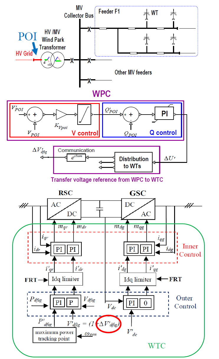
Putting the layers in series gives the complete path from a plant-level request to physical action, shown in Figure 1: the outer loop forms a current reference from a power or voltage error, the limiter caps it to the converter’s capability, the inner loop forms a voltage reference from the current error, and that voltage is realised — by PWM switching in a detailed model, or mathematically in an average-value model. The converter never “sets reactive power” as a primitive: it sets current and voltage behaviour, and the reactive power follows.

DFIG converter-control block diagram: the plant-controller (WPC/PPC) reference enters the wind-turbine converter control; the rotor-side converter (RSC) and grid-side converter (GSC) each run an outer power/voltage loop producing a dq current reference, a current limiter, and a fast inner current loop producing the dq voltage reference realised by PWM or an average-value model.
Figure 1 — DFIG converter control. The plant-controller (WPC/PPC) reference enters the wind-turbine converter control; the RSC and GSC each run an outer loop (active power or voltage / dc-link) → current limiter → inner current loop, ending in the dq voltage reference realised by PWM switching or an average-value model.

Section 4

The DFIG: two converters and a dc link

A doubly-fed induction generator has its stator connected directly to the grid and its rotor fed through a back-to-back ac–dc–ac converter — a rotor-side converter (RSC) and a grid-side converter (GSC) sharing a dc link. The two have distinct duties: the RSC controls the machine’s electromagnetic behaviour — its active power/torque and its terminal voltage or reactive power — while the GSC mainly holds the dc-link voltage and passes the rotor slip power to the grid. The wider machine and back-to-back topology is covered in the wind-park architecture guide; here the focus is the control inside each converter.

Table 1 — The two converters of a DFIG and what each dq current component controls, in the reference frames used by this generic model.
ConverterReference frameOne axis controlsOther axis controls
RSC (rotor-side)Stator-flux frame\(q\)-axis current \(i_{qr}\) → active power (from MPPT)\(d\)-axis current \(i_{dr}\) → wind-turbine terminal positive-sequence voltage / reactive power
GSC (grid-side)Grid-voltage frame\(d\)-axis current \(i_d\) → dc-link voltage\(q\)-axis current \(i_q\) → grid-side voltage / reactive support (reactive ref \(\approx 0\) in normal operation)

The axis mapping in the table holds only for the stated reference frames and sign conventions; in a different frame or convention the same current component can carry a different meaning, so it should not be transplanted to another tool without re-checking. Throughout this page, positive active power is generation from the turbine to the grid, and positive reactive power is injection from the plant into the grid.

Section 5

The rotor-side converter (RSC)

The RSC is the machine’s controller, and it runs two outer channels in parallel — two regulated dq current components. One sets how much active power (or torque) the machine delivers; the other sets the machine’s terminal voltage and reactive behaviour. Each channel produces a current reference for its axis, and the inner current loop then makes the rotor converter follow those targets. This is why the plant-controller reactive reference ultimately acts here. Changing the rotor current changes the air-gap flux and torque and the stator’s reactive exchange with the grid, so the terminal voltage and reactive power change with it — that is what “changing the machine’s electromagnetic state” means in practice.

Section 6

Why active and reactive map to different dq axes

A point that often confuses readers of these diagrams: which axis means “active” and which means “reactive” depends on the chosen reference frame. A reference frame is a rotating set of axes the controller works in, so that ac quantities appear as two steady dc-like components. The RSC uses the stator-flux frame — axes aligned with the machine’s stator flux — and in that frame the \(q\)-axis current is associated with active-power control and the \(d\)-axis current with reactive-power / voltage control. That association is the convention this EMTP® model uses; it follows from the alignment and sign convention chosen, and is not a universal rule. In a different frame — for example the GSC’s grid-voltage frame, aligned with the grid voltage vector — the same-looking current can carry the opposite meaning, so always read the dq labels against the frame the controller uses.

Section 7

The active-power loop: MPPT

The RSC’s active-power channel takes its reference from maximum power point tracking (MPPT) — the logic that, for the available wind and rotor speed, aims to extract the maximum aerodynamic power. The turbine/generator speed is measured, the MPPT logic sets the desired power for that speed, and the result is the active-power reference. The loop compares it with the measured active power, generates a current reference, limits it, and hands it to the inner current loop. Two boundaries are worth keeping in mind. First, MPPT only sets a reference: the power actually delivered is still bounded by the machine and converter ratings, the current limits, the available wind and any protection logic. Second, MPPT and this current loop are not the whole turbine — the aerodynamic rotor, pitch system and shaft dynamics are separate mechanical models (see wind-turbine control); the RSC current loop does not by itself determine all of the turbine’s mechanical behaviour.

Section 8

The reactive / voltage loop: where the plant request lands

The RSC’s other channel is the one relevant to plant-level reactive behaviour. Its input — depending on the selected control mode — is a voltage-reference correction, a reactive-power reference or a local voltage/reactive target from the plant controller. It compares that with the measured local quantity, and the error produces a current reference on the appropriate dq axis. When the plant controller asks for more reactive support, it is this reference that moves: the rotor current reference changes, the machine’s electromagnetic state changes with it, and the reactive/voltage behaviour at the wind-turbine terminal follows. That local response is not the same as the plant-level target — the RSC acts at the machine terminal, while the plant-controller target is usually measured at the POI — so the local reactive output reaches the POI figure through the unit transformer and the collector grid. This is the physical implementation of the plant-controller request, the point where the supervisory command from the plant-controller implementation becomes a real current reference.

Section 9

The grid-side converter (GSC)

The GSC’s primary job is to keep the dc-link voltage stable. One of its dq channels regulates that voltage: the dc-voltage error is passed through a proportional–integral (PI) controller whose output is a current reference.

\[ i_d^{*} = K_{p,dc}\,(V_{dc}^{*} - V_{dc}) + K_{i,dc}\!\int (V_{dc}^{*} - V_{dc})\,dt \]
\(i_d^{*}\)
d-axis current reference of the GSC; its sign depends on the grid-voltage-frame and power-flow convention, so the control direction should be read against the chosen convention
\(V_{dc}^{*}\)
dc-link voltage reference (set-point)
\(V_{dc}\)
measured dc-link voltage
\(K_{p,dc},\ K_{i,dc}\)
proportional and integral gains of the dc-voltage regulator — distinct from the current-loop gains \(K_{p,i},\ K_{i,i}\) below

The d-axis current maintains the dc-link voltage; whatever power the rotor side pushes into or pulls out of the dc link, this loop adjusts the grid-side current to balance it.

The GSC’s other (q-axis) channel is, in this generic DFIG control, normally held near unity power factor — its reactive reference is essentially zero in normal operation — because the turbine’s steady reactive support and terminal-voltage control are done by the RSC. This is a common generic-model assumption rather than a universal OEM rule: some implementations do let the GSC provide reactive support, or apply different priority logic. In some fault ride-through (FRT) implementations the GSC may also contribute reactive current according to the model’s current-limit and priority logic — useful because the induction machine can itself absorb reactive power during a fault (it still needs magnetising flux while the terminal voltage is depressed, and crowbar action makes it worse). That reactive absorption is a DFIG-specific complication a fully converter-decoupled Type-4 turbine does not have. The GSC’s active current, by contrast, is set by dc-link balance rather than by a generation set-point: it carries the rotor slip power to or from the grid, so it is near zero only close to synchronous speed and grows with slip — up to roughly 0.2–0.3 pu at maximum slip. The real electromechanical power still comes from the machine via the RSC and the stator; the GSC only routes the rotor’s share.

The GSC connects to the grid through a line inductor (choke), usually with an ac harmonic filter to improve power quality. The choke is not just a detail: it is the very inductance the current loop is tuned around, and it sets the current-loop bandwidth. With the filter it also shapes the converter’s harmonic impedance and its stability interactions with the grid, so these elements should not be removed casually from an electromagnetic transient (EMT) or frequency-domain study — they matter for harmonic and sub-synchronous interaction work, which those dedicated pages cover.

Section 10

Current limits: physically essential

Once an outer loop has produced a current reference, it must be limited before it reaches the inner loop, because the converter cannot produce infinite current. Semiconductor, thermal, magnetic and protection constraints all cap what the hardware can deliver, so however large a response the controller “wants”, the current reference is bounded to the achievable maximum.

\[ \underline{i}^{*}_{\text{lim}} = \begin{cases} \underline{i}^{*}, & |\underline{i}^{*}| \le i_{\max} \\[4pt] i_{\max}\,\dfrac{\underline{i}^{*}}{\,|\underline{i}^{*}|\,}, & |\underline{i}^{*}| > i_{\max} \end{cases} \]
\(\underline{i}^{*}\)
commanded current reference (complex / dq vector)
\(\underline{i}^{*}_{\text{lim}}\)
limited current reference passed to the inner loop
\(i_{\max}\)
maximum current magnitude the converter may produce, on its own converter base (the RSC and GSC have separate ratings and bases), set by rating and role

The values are illustrative only: around 1.1–1.2 pu on the converter’s own base is common, and a converter sized only for dc-link balancing may be lower, on the order of 0.3 pu — but actual limits depend on the converter rating, thermal design, overload capability and OEM settings, and are not meaningful without stating the base. Note too that this formula simply scales the whole current vector when it exceeds \(i_{\max}\); active/reactive-current priority or separate per-component limiting is additional logic, described next.

Without limiting, the controller would demand impossible current, the voltage reference would become unrealistic, and protection or numerical trouble would follow — and the model would no longer represent the converter’s real capability. The limiter is therefore not a refinement but a physically essential block.

Beyond simple scaling, a current-priority rule decides which component keeps its share when the total is capped. In normal operation the active currents are usually prioritised — the RSC tracks its MPPT power, the GSC holds the dc link — and reactive demand takes the remaining margin; during fault ride-through the priority typically shifts toward reactive current for voltage support. The exact priority logic is model- and grid-code-dependent, so it should be checked against the EMTP® generic model or the OEM model rather than assumed — this page only notes that priority can change during faults; the fault logic itself belongs to the dedicated FRT page. The DFIG’s RSC and GSC inner loops mirror the machine-side and grid-side loops of the full-scale converter, and the priority change is realised through the current-reference and current-limit logic, not a different controller.

Section 11

The inner current loop and PWM

With a limited current reference in hand, the fast inner loop compares it with the measured current and, through a PI regulator (usually with a decoupling / feed-forward term), produces the dq voltage reference the converter must apply:

\[ v_{dq}^{*} = K_{p,i}\,(i_{dq}^{*} - i_{dq}) + K_{i,i}\!\int (i_{dq}^{*} - i_{dq})\,dt \;+\; v_{dq}^{\text{ff}} \]
\(v_{dq}^{*}\)
converter voltage reference (dq components)
\(i_{dq}^{*}\)
limited current reference (the request the loop tracks)
\(i_{dq}\)
measured converter current
\(v_{dq}^{\text{ff}}\)
decoupling / feed-forward voltage term; depending on the converter side and reference frame it may compensate the dq cross-coupling, the grid or stator voltage, rotor-speed (slip) terms or the filter voltage
\(K_{p,i},\ K_{i,i}\)
gains of the fast current regulator (distinct from the dc-loop gains above)

This is the most important fast electrical loop: it computes the dq voltage needed for the output current to follow its reference.

The two gains \(K_{p,i}\) and \(K_{i,i}\) are not free numbers to be tuned by trial. A common and robust choice for the RSC current loop is internal-model control (IMC), which places the closed loop as a single first-order response of chosen bandwidth \(\omega_c\) by cancelling the machine’s own electrical dynamics. To do this on the induction machine it is convenient to use the Γ (gamma) representation, which folds the stator leakage into the magnetising branch — with no loss of accuracy — so the rotor sees a single series resistance \(R_R = \sigma^{2} R_r\) behind a total leakage inductance. The IMC gains then follow directly from that lumped circuit:

\[ K_{p,i} = \omega_c\,L_{\lambda}, \qquad K_{i,i} = \omega_c\,R_R, \qquad R_R = \sigma^{2}\,R_r \]
\(\omega_c\)
chosen current-loop bandwidth (rad/s); it sets how fast the loop tracks its reference and, with it, both gains scale
\(L_{\lambda}\)
total leakage inductance of the Γ model — the effective series inductance the rotor current sees
\(R_R\)
Γ-model rotor resistance, \(\sigma^{2} R_r\), that lumps the stator-leakage effect into the rotor branch
\(\sigma,\ R_r\)
the Γ-model turns/leakage factor and the physical rotor resistance

Because the gains are the plant parameters scaled by one bandwidth, the loop keeps a consistent response across operating points. The regulator is completed by a rotor-speed-dependent feed-forward term that decouples the dq cross-coupling introduced by the rotating frame, so \(v_{dq}^{\text{ff}}\) above is not a fixed offset but tracks the measured rotor speed.

The dq voltage reference is transformed into an abc voltage reference — a sinusoidal quantity the converter should produce at its terminals. In a switching model, PWM compares it with a carrier to generate the insulated-gate bipolar transistor (IGBT) gate pattern; in an average-value model, the same voltage reference is applied directly, without resolving individual switching events. Either way the inner loop is the direct actuator of current behaviour. One caveat: although the RSC and GSC share this cascade form, they are not the same controller — the measured currents, the reference frame, the plant interface, the controlled object and the feed-forward terms all differ between the two sides, so the single formula above is a template, not a one-size-fits-all block.

Section 12

What changes when the plant asks for more reactive power

Now the opening question has a complete answer, best read as what changes physically, in order. The plant controller changes a reference; the converter’s outer reactive/voltage loop turns that into a new dq current reference; the limiter caps it to the converter’s capability; the inner loop turns the current error into a new dq voltage reference; and that voltage is realised by PWM switching or an average-value model. Only then does the physical layer move: the converter current changes, the machine’s (or grid-side) electromagnetic behaviour changes with it, and the POI reactive power settles toward the new target — as far as the converter’s capability and current limits allow. The plant controller asks at the reference level; the converter executes through dq current control.

Section 13

Key points

  1. Converter control is a cascade: the plant reference becomes a current reference, then a voltage reference, then switching — the plant controller never commands current or gate pulses directly.

  2. The RSC and GSC have different duties: the RSC controls the machine (active power from MPPT, terminal voltage/reactive on the other axis); the GSC mainly holds the dc-link voltage.

  3. The dq-axis meaning depends on the reference frame (stator-flux for the RSC, grid-voltage for the GSC) and the sign convention — read the labels against the frame.

  4. Current references are limited before the inner loop; the limits and the active/reactive priority are physically essential and model-dependent.

  5. The inner loop produces the dq voltage reference, realised by PWM switching or an average-value model. For the surrounding model and supervisory layer, see the wind-park architecture and plant-controller reactive power control guides.

References

References

  1. EMTP® Documentation and Application Notes. Powersys / EMTP®.
Built on EMTP® · Expert spotlight
Portrait of Henry Gras, Chief Operating Officer of PGSTech

Henry Gras

Chief Operating Officer, PGSTech · Montréal, Canada

Henry Gras delivers the EMTP® University course “EMT Simulation and Analysis of Large-Scale Power Systems with Renewables” and works daily with the tool this article is written around.

Henry is based in Montréal, where he is Chief Operating Officer of PGSTech, the company responsible for EMTP® engineering services, commercialisation and continuing software development. He holds a master’s degree from Polytechnique Montréal, where he worked on electrical-machine research, and previously completed an engineering degree at École Centrale de Lyon in France.

Readers who want a structured programme on EMT simulation of large-scale power systems with renewables will find his EMTP® University course an excellent next step.

Henry’s technical expertise covers electromagnetic transient simulation, renewable-energy integration, power-system modelling, electrical machines, protection and specialist transient studies including TRV, transformer energisation, ferroresonance, insulation coordination and power quality.

Thirty-Part Technical Series

EMTP® Renewable Energy Modelling

A thirty-part guide to modelling wind, PV and full-converter plant in EMTP® — sources and turbines, converter and plant control, sequence control under faults, protection, and weak-grid and SSCI stability.

Part 7 Reading now

DFIG Converter Control

From the plant reference to PWM through the rotor- and grid-side dq current loops.

Series progress 7 of 30

