Renewable Modelling · Type-4 / PV GSC Control

Full-Scale Converter GSC Control in EMTP®: dc-Link Voltage and Reactive Support (Type-4 Wind and PV)

The machine-side converter guide showed how wind power reaches the dc link. This page takes the grid side. The grid-side converter (GSC) is the plant’s final grid-facing actuator, and this guide works through its control: the dc-voltage loop that doubles as the active-power channel, the proportional voltage regulator on the reactive channel, the current limiter that arbitrates during faults, and the inertia-emulation tuning of the dc-voltage loop. The grid-side control philosophy is similar for Type-4 wind and PV, but the dc-side source and its upstream controls differ.

Reading time ≈ 20 min · dc-link voltage, reactive support & tuning

The machine-side converter guide followed wind power as far as the dc link. The grid-side converter (GSC) takes it from there. It is the plant’s grid interface, and it has two clear jobs: keep the dc-link voltage close to its reference, and provide the grid-side reactive or voltage support the plant controller (PPC) requests. The first job is what normally pushes the active power on into the grid; the second is how the plant meets its voltage and reactive targets. The same generic GSC structure can represent both Type-4 (full-converter) wind turbines and photovoltaic (PV) plants: the grid-side control philosophy is the same, while the dc-side source and its upstream controls differ — provided the source, ratings, limits, control priorities and plant-controller interface are configured for each case.

Abbreviations used on this page
GSCGrid-side converter
MSCMachine-side converter
FSCFull-scale converter
PPCPlant (park) controller
\(V_{dc}\)dc-link (dc-bus) voltage
FRTFault ride-through
PIProportional–integral controller
\(K_V\)Voltage-regulator gain (q-axis)
\(V^{+}\)Positive-sequence terminal voltage
\(i_{dg},\ i_{qg}\)d- and q-axis grid-side currents
PWMPulse-width modulation
Idq / dqdq current limiter / direct–quadrature rotating frame
Type-4Full-converter wind turbine
PVPhotovoltaic (solar)
POIPoint of interconnection
ac / dcAlternating / direct current
puPer unit
EMTP®Electromagnetic Transients Program
EMTElectromagnetic transient (time domain)
Key idea
  1. The GSC is the plant’s grid interface and its final grid-facing actuator: everything the plant sends to, or is asked of by, the grid is executed here, through the two dq current channels below.
  2. The dc-voltage loop is really an active-power loop: a PI on the dc-voltage error sets the d-axis current reference (dc-voltage error \(\rightarrow i_{dg}'\)), so when more source power arrives and the dc voltage rises, the GSC normally exports more active power to pull it back — within current limits, priority and FRT logic. The dc capacitor is the energy buffer.
  3. Reactive / voltage support is the q-axis channel: a proportional voltage regulator turns the plant-side voltage reference versus the measured positive-sequence voltage into a q-axis current (\(i_{qg}'=K_V(V'-V^{+})\)) — proportional only, because the plant controller already supplies the slower integral action.
  4. Both current references pass an Idq limiter (with an FRT input for fault priority) before the fast inner current PI; the dc-voltage loop is tuned by inertia emulation (\(k_p=2\xi\omega_0\,2H_{cdc}\), \(k_i=\omega_0^{2}\,2H_{cdc}\)). The same generic GSC serves Type-4 wind and PV; only the dc-side source and upstream controls differ.
Key terms used on this page
01Grid-side converter
The GSC: the converter facing the grid; it holds the dc-link voltage and supports terminal voltage / reactive.
02dc-link voltage control
Keeping \(V_{dc}\) near its reference (~1 pu) by balancing the power into and out of the dc capacitor.
03d-axis current
\(i_{dg}\): the active-power channel; the dc-voltage PI sets its reference.
04q-axis current
\(i_{qg}\): the reactive / voltage-support channel; set by a proportional voltage regulator.
05Voltage-regulator gain
\(K_V\): converts a positive-sequence voltage error into the q-axis current reference.
06Positive-sequence voltage
\(V^{+}\): the balanced component of the terminal voltage, estimated from measured GSC quantities; during unbalanced faults it differs from the phase voltages, so which signal the FRT and reactive control use matters.
07Idq limiter
Caps the dq current references to the converter capability, prioritising during faults via the FRT input.
08FRT priority
During a fault, the limiter allocates the limited current between active and reactive support.
09Inertia emulation
Tuning the dc-voltage loop by treating the dc-link stored energy as an inertia-like element.
10dc-link energy constant
\(H_{cdc}=E_{cdc}/S_{wt}\): the stored dc energy normalised by the plant rating.
11Outer / inner loops
Outer loops produce dq current references; the fast inner loop produces the dq voltage references.
12Energy buffer
The dc capacitor: its voltage rises if more power enters than leaves, and falls if less.

Section 1

The grid-side converter: the plant’s grid interface

A full-converter plant has a source side, where power is created or extracted, and a grid side, where it is injected into the ac system, with the dc link between them. The GSC is the device that interfaces the dc link to the grid. Where the MSC controls the generator and feeds the dc link, the GSC takes whatever the dc link receives and manages how it is delivered to the network — and shapes the plant’s reactive behaviour at the same time.

Where the GSC sits

The MSC delivers power into the dc link; the GSC takes whatever the dc link holds, delivers it to the grid as active power, and shapes the plant’s reactive behaviour on the way. Everything on this page is how it manages that hand-off — the same generic block for Type-4 wind and PV.

Section 2

Two jobs, two channels

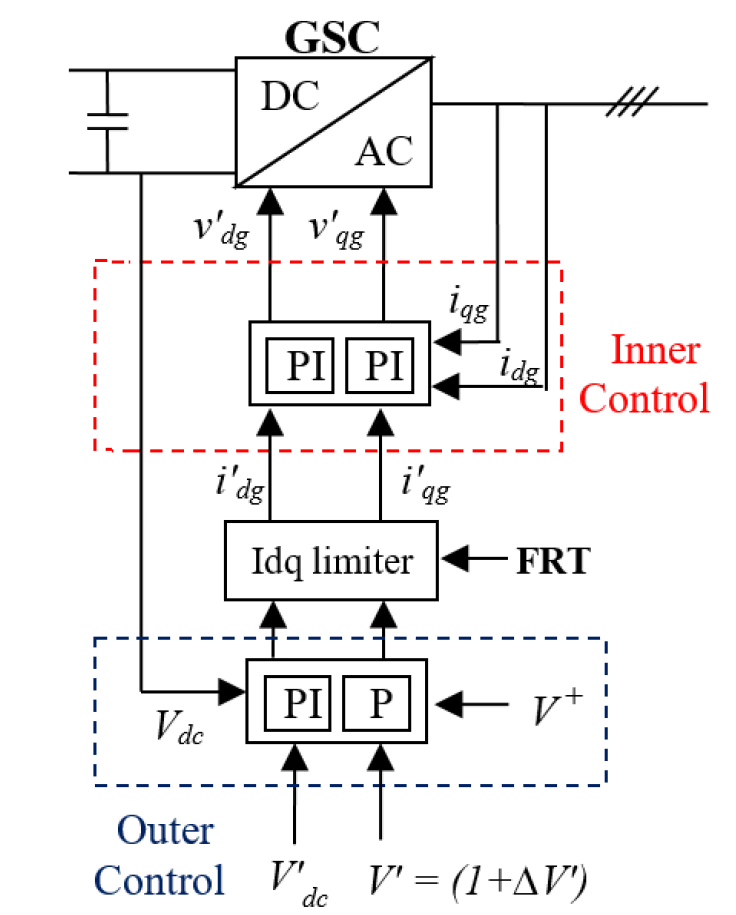
The two functions map cleanly onto the two dq current channels of the converter. The d-axis current carries the active power and is used to regulate the dc-link voltage; the q-axis current carries the reactive support and is set from a voltage / reactive reference. So the GSC runs two outer loops — a dc-voltage loop and a voltage / reactive loop — each producing a current reference, with a single fast inner current loop underneath. The figure shows the arrangement.

Schematic of the grid-side converter control: an outer dc-voltage PI producing the d-axis current reference, a proportional voltage regulator producing the q-axis current reference, the dq current (Idq) limiter with its fault-ride-through input, and the inner dq current PI loops producing the converter voltage references for PWM or an average-value model.
Figure 1 — Grid-side converter control. The dc-voltage PI sets the d-axis current reference; the proportional voltage regulator sets the q-axis current reference; the dq current (Idq) limiter, with its FRT input, bounds them; and the inner dq current PI produces the converter voltage references, realised by pulse-width modulation (PWM) or an average-value model.

Section 4

The dc-voltage loop is an active-power loop

Here the d-axis reference current is produced by the dc-voltage PI regulator. This assumes a grid-voltage-oriented frame (with \(v_q\approx 0\)), in which the d-axis current is the active-power channel; in another convention the axis mapping or signs may differ. Throughout, the prime marks a reference or target value and the unprimed symbol is the measured value. The measured dc voltage is compared with its reference and the error drives a PI whose output is the d-axis current reference:

\[ i_{dg}' = K_{p,dc}\,(V_{dc} - V_{dc}') + K_{i,dc}\!\int (V_{dc} - V_{dc}')\,dt \]
\(i_{dg}'\)
d-axis (active-power) current reference of the GSC; positive means active current injected into the grid
\(V_{dc}'\)
dc-link voltage reference — normally 1 pu on the dc-link voltage base
\(V_{dc}\)
measured dc-link voltage
\(K_{p,dc},\ K_{i,dc}\)
proportional and integral gains of the dc-voltage regulator (distinct from the inner current-loop gains \(K_{p,i},\ K_{i,i}\) below)

With positive \(i_{dg}\) defined as injection into the grid, a dc voltage above reference gives a positive error and commands more active export, pulling \(V_{dc}\) back down; under the opposite current-direction convention the error term would be \((V_{dc}'-V_{dc})\). Either way, correcting the dc voltage means commanding active current — the dc-voltage loop is the GSC’s active-power loop.

So the mechanism is a clean chain: the dc-voltage loop creates an active-current reference, which changes the active power exported to the grid, which restores the dc voltage. The dc-voltage loop is, in effect, the GSC’s active-power loop.

Section 5

How the GSC passes active power to the grid

It is worth being explicit about the GSC’s central physical role. The machine side (or the PV dc source) can put power into the dc link, but that does not yet mean the grid has received it. The GSC is the element that actually converts that dc-side power into three-phase ac current injected into the network. So the path is: the source side creates dc-link power; the GSC senses the dc-voltage tendency; the GSC adjusts the d-axis current; and more or less active power is pushed into the grid. The GSC is the bridge from source-side power to grid-side power — and it is the dc-voltage regulation that makes the transfer happen automatically.

Section 6

Reactive / voltage support: the q-axis channel

The second outer loop produces the reactive support. The q-axis current reference is calculated by a proportional voltage regulator acting on the difference between the plant-side voltage reference and the measured positive-sequence terminal voltage. “Terminal” here means a local GSC measurement point — the converter or turbine terminal, or the low-voltage transformer side — not the point of interconnection (POI): the plant controller regulates the POI, and the GSC executes that request locally.

\[ i_{qg}' = K_V\,(V' - V^{+}) \]
\(i_{qg}'\)
q-axis (reactive) current reference of the GSC; the sign of \(i_{qg}'\) and of reactive power depends on the dq and project/tool sign convention
\(K_V\)
voltage-regulator gain (q-axis)
\(V'\)
positive-sequence terminal-voltage reference from the plant controller — a voltage target / reference correction, not a POI measurement
\(V^{+}\)
measured positive-sequence terminal-voltage magnitude, derived (dq-based, filtered) in the “compute variables” block from the GSC ac voltages

If the measured voltage is below target, \(i_{qg}'\) moves to inject more reactive current, which usually raises the local voltage; above target, it absorbs. “Usually” matters: the actual effect depends on the network impedance, the sign convention, transformer connections, cable charging, current limits and the fault condition, so reactive injection does not always raise voltage by the expected amount. This q-axis channel is the converter-level execution of the plant-controller request, which may be a voltage, reactive-power or power-factor target.

Section 7

Why the q-axis loop is only proportional

The reactive channel here uses a proportional regulator, not a full PI — and that is deliberate. The plant controller already contains the slower, supervisory PI action that drives the point-of-interconnection error to zero, so the converter-side reactive channel does not need a second integrator. A proportional conversion from voltage error to current reference is enough: the local converter loop should be fast, the plant controller handles the slow steady-state correction, and stacking integral action in several nested loops would only complicate the behaviour. So the outer q-axis control is simply voltage error × gain → current reference, and the inner loop handles the fast tracking. This is the structure of this generic model; OEM implementations may instead use droop, a full PI, a deadband, a Volt–VAR curve, measurement filters or extra limiters on the same channel.

Section 8

Outer and inner loops

As on the machine side, the GSC separates a slower outer control from a fast inner one. The outer loops turn the dc-voltage error into \(i_{dg}'\) and the voltage / reactive error into \(i_{qg}'\). The inner current loop then compares those references with the measured currents \(i_{dg}\) and \(i_{qg}\); it does not create current directly but produces the dq voltage references the converter applies, realised through PWM or an average-value model:

\[ v_{dqg}' = K_{p,i}\,(i_{dqg}' - i_{dqg}) + K_{i,i}\!\int (i_{dqg}' - i_{dqg})\,dt \]
\(v_{dqg}'\)
dq voltage reference applied by the grid-side converter
\(i_{dqg}'\)
dq current reference (after limiting)
\(i_{dqg}\)
measured dq grid-side currents
\(K_{p,i},\ K_{i,i}\)
proportional and integral gains of the inner current loop (distinct from the dc-voltage-loop gains above)

The hierarchy is the familiar one: outer control → \((i_{dg}',\,i_{qg}')\) → inner current control → \((v_{dg}',\,v_{qg}')\) → PWM or an average-value model. In a switching model PWM generates the gate pattern; in an average-value model the same voltage reference is applied without resolving individual switching events.

Section 9

The Idq limiter and fault ride-through

Between the outer and inner loops sits a dq current limiter (the Idq limiter), and it is not an optional detail. It bounds the combined d-axis and q-axis current request so the converter’s total current capability is not exceeded. Depending on the model it may scale the whole current vector back, apply separate limits to each component, or enforce an active-versus-reactive priority — the exact rule is model-specific and should be checked. Either way it is the interface between what the outer loops would like and what the hardware can deliver, and it decides how the converter prioritises its current when dc-voltage support, reactive support and fault response all compete for the same limited capability.

That is why the limiter has a fault ride-through (FRT) input, and this is the strongest practical message of the page: during a fault the converter may need reactive current for voltage support, active current for dc-link control, and headroom for hardware protection all at once — and it cannot satisfy all three. The Idq limiter decides the feasible combination. The exact priority is grid-code- and model-dependent: some models prioritise reactive current during voltage dips, others preserve dc-link control or active current within limits. And because the GSC may then be unable to export all the incoming source power, the dc voltage can rise — so a dc chopper, active-power reduction, pitch action (wind), PV curtailment, converter blocking or protection may be needed, depending on the model, to keep the dc link safe.

In this generic model the choice is made by a threshold on the measured positive-sequence voltage. Under normal operation the limiter gives priority to active current \((i_{dg})\): the d-axis reference keeps its full share of the current budget and the reactive channel takes what is left, matching the everyday job of holding the dc link and exporting power. When \(V^{+}\) falls below a defined FRT-entry threshold \(V_{\text{FRT,on}}\), the FRT function reverses the priority to reactive current \((i_{qg})\) by swapping the d- and q-axis current limits, so voltage support is now served first and the active channel is capped with the remaining headroom. The swap is a discrete change driven by a single measured signal, which is one reason the positive-sequence estimate and the threshold value are worth checking — they set the exact voltage at which the converter flips from active-priority to reactive-priority behaviour.

Section 10

Tuning the dc-voltage loop by inertia emulation

The dc-voltage PI is tuned with structure rather than by trial and error. The dc capacitor stores energy, so the dc-voltage loop can be tuned by treating that stored dc-link energy as an inertia-like storage term — the same mathematics used for rotating inertia, applied to the capacitor. The gains then follow from a chosen natural frequency and damping factor:

\[ k_p = 2\xi\omega_0\,(2H_{cdc}), \qquad k_i = \omega_0^{2}\,(2H_{cdc}), \qquad H_{cdc} = \frac{E_{cdc}}{S_{wt}} \]
\(k_p,\ k_i\)
proportional and integral gains of the dc-voltage loop (in the per-unit convention of the model)
\(\omega_0\)
chosen natural frequency of the closed loop (rad/s)
\(\xi\)
chosen damping factor of the closed loop (dimensionless)
\(H_{cdc}=E_{cdc}/S_{wt}\)
dc-link stored-energy constant (s) — an “inertia” time constant for the dc bus
\(E_{cdc}\)
energy stored in the dc-bus capacitor (J, \(=\tfrac{1}{2}CV_{dc}^{2}\))
\(S_{wt}\)
rated power base (VA) — the EMTP® notation \(S_{wt}\) is used even for PV; use the plant/turbine or converter rating the model is normalised to

This gives a structured starting point rather than arbitrary values: pick the desired \(\omega_0\) and \(\xi\), and the gains follow from the dc-link energy and the rated power. The values are not universal, though — they depend on the project and model, and must be checked against the current limits, dc-link capacitance, grid strength, measurement delays and FRT behaviour, then validated in the EMT model.

Table 1 — The inertia-emulation tuning quantities of the dc-voltage loop, and the reactive-channel gain.
SymbolQuantity
\(\omega_0\)Natural frequency of the closed-loop system
\(\xi\)Damping factor of the closed-loop system
\(H_{cdc}\)dc-link stored-energy constant (s), \(E_{cdc}/S_{wt}\)
\(E_{cdc}\)Energy stored in the dc-bus capacitor (J)
\(S_{wt}\)Rated power base (VA) — plant/turbine or converter rating (EMTP® notation, used even for PV)
\(K_V\)q-axis voltage-regulator gain
\(V',\ V^{+}\)Positive-sequence voltage reference and measurement

Section 11

The same GSC for Type-4 wind and PV

The control here is shared between Type-4 wind turbines and PV plants because the grid-side philosophy is the same in both: each has a dc link and an inverter tied to the ac network, one channel managing the dc-link active-power balance and the other the voltage / reactive support. What differs is the dc-side source and its upstream controls — a wind turbine and machine, or a PV dc source — so the same generic grid-side structure can represent both, provided the source, ratings, limits, priorities and plant-controller interface are configured correctly for each case.

This is a deliberately simplified picture. A manufacturer model may add decoupling terms, resonance controllers, current-priority logic, detailed FRT behaviour, measurement delays and feed-forward compensation. One caution in particular: because the GSC controls voltage and reactive current through a grid-oriented frame, on a weak grid the grid impedance, PLL dynamics and control delays can interact and affect stability, so the tuning above may need extra care or added damping. But the essential structure — a dc-voltage outer loop, a reactive / voltage outer loop, a current limiter, an inner current control and PWM or average-value execution — remains, so understanding it is enough to reason about a real plant model and discuss it sensibly with a model provider.

Section 12

The full GSC control chain

Put together, the grid-side control is two reference-forming paths into a shared inner loop. The dc-voltage error forms the active-current reference \(i_{dg}'\); the voltage error \(V'-V^{+}\) forms the reactive-current reference \(i_{qg}'\); the Idq limiter enforces the converter’s capability and its FRT priority on the pair; the inner current PI tracks the limited references; and the converter applies the resulting dq voltage references through PWM or an average-value model. Together with the machine-side converter the picture is complete: the MSC passes the available source power into the dc link and the GSC delivers it to the grid, with the dc link the coupling point between them.

Section 13

Key points

  1. The GSC regulates the dc-link voltage — a PI on the dc-voltage error sets the d-axis (active-power) current, so exporting active power is how the dc voltage is held and how the plant’s power reaches the grid.

  2. The q-axis channel provides voltage / reactive support — a proportional regulator turns \(V'-V^{+}\) into the reactive-current reference, proportional-only because the plant controller supplies the integral action.

  3. The Idq limiter is essential: it bounds the dq current references to the converter capability and, via its FRT input, allocates the limited current during faults.

  4. Under FRT the current priority changes (reactive vs active vs dc-link), by grid-code- and model-dependent logic; the dc link may then need a chopper or curtailment.

  5. The dc-voltage PI is tuned by inertia emulation from the dc-link energy and the rated power, then validated in the EMT model. The same generic scheme serves Type-4 wind and PV. See the full-scale converter, machine-side converter and plant-controller guides.

References

References

  1. EMTP® Documentation and Application Notes. Powersys / EMTP®.
Built on EMTP® · Expert spotlight
Portrait of Henry Gras, Chief Operating Officer of PGSTech

Henry Gras

Chief Operating Officer, PGSTech · Montréal, Canada

Henry Gras delivers the EMTP® University course “EMT Simulation and Analysis of Large-Scale Power Systems with Renewables” and works daily with the tool this article is written around.

Henry is based in Montréal, where he is Chief Operating Officer of PGSTech, the company responsible for EMTP® engineering services, commercialisation and continuing software development. He holds a master’s degree from Polytechnique Montréal, where he worked on electrical-machine research, and previously completed an engineering degree at École Centrale de Lyon in France.

Readers who want a structured programme on EMT simulation of large-scale power systems with renewables will find his EMTP® University course an excellent next step.

Henry’s technical expertise covers electromagnetic transient simulation, renewable-energy integration, power-system modelling, electrical machines, protection and specialist transient studies including TRV, transformer energisation, ferroresonance, insulation coordination and power quality.

Thirty-Part Technical Series

EMTP® Renewable Energy Modelling

A thirty-part guide to modelling wind, PV and full-converter plant in EMTP® — sources and turbines, converter and plant control, sequence control under faults, protection, and weak-grid and SSCI stability.

Part 10 Reading now

Full-Scale Converter GSC Control

dc-link voltage regulation and reactive support on the grid side of a full-scale converter.

Series progress 10 of 30


