
Renewable Modelling · DFIG Negative-Sequence Compensation

DFIG Negative-Sequence Compensation through the GSC in EMTP®

Reducing oscillating air-gap torque under unbalanced grid conditions

A DFIG is sensitive to unbalanced grid voltage because its stator is directly connected to the network. Negative-sequence voltage can drive rotor-current components and produce a twice-frequency air-gap torque pulsation, increasing cyclic mechanical stress on the shaft, gearbox and drive train. One decoupled-sequence-control route uses the grid-side converter to compensate the negative sequence: the GSC injects a calculated negative-sequence current at the grid side, so the total grid current stays balanced and the dc-link ripple at twice grid frequency is eased — while the rotor-side converter does the more direct work on the machine’s torque. What follows sets out the method, its reference scheme, and why the fault-ride-through requirement always comes first.

Reading time ≈ 18 min · air-gap torque & GSC negative-sequence injection

Grid unbalance is harder on a DFIG than on a full-converter turbine, and the reason is structural: the DFIG stator sits directly on the grid, so a negative-sequence voltage acts straight on the machine. The result is high-frequency components in the rotor currents and, more damagingly, a torque pulsation at twice grid frequency that increases cyclic mechanical stress on the gearbox and shaft. One way to ease it is a decoupled-sequence-control method in which the grid-side converter compensates the negative sequence, injecting a calculated negative-sequence current at the grid side so the machine sees less imbalance. It is the DFIG-specific cousin of the general DSC already covered for the full-scale converter.

Abbreviations used on this page
DFIGDoubly-fed induction generator
IGInduction generator (the machine)
RSCRotor-side converter
GSCGrid-side converter
DSCDecoupled sequence control
\(2\omega\)Twice grid frequency (second harmonic)
\(+\,/\,-\)Positive- / negative-sequence quantities
FRTFault ride-through
PLLPhase-locked loop
SSCISub-synchronous control interaction
\(I_g\)Grid-side current
EMTP®Electromagnetic Transients Program
Key idea
  1. Unbalanced operation drives high-frequency rotor currents and a 2ω air-gap torque pulsation that increases cyclic mechanical stress on the gearbox, shaft and drive train (and ripples the dc link). A DFIG suffers more than a Type-4 turbine because its stator is directly grid-connected.
  2. The primary objective is to reduce that oscillating air-gap torque. It can be done via the RSC, the GSC, or both; the implemented method uses the GSC to compensate — injecting a calculated negative-sequence current at the grid side, so the grid current carries both sequences, \(\underline{i}_g=\underline{i}_g^{+}+\underline{i}_g^{-}\).
  3. The GSC references split: positive sequence = the normal control references; negative sequence = the machine’s negative-sequence currents (\(i_{dg}^{-\prime}=i_{dwt}^{-}\), \(i_{qg}^{-\prime}=i_{qwt}^{-}\)).
  4. The references are revised for the converter limit and, above all, the FRT requirement — grid-code positive-sequence reactive current comes first, the compensation uses the remaining reserve. It remains a specialised method (complex, sequence-extraction- and PLL-sensitive, with grid-code requirements still developing) and ties into impedance / SSCI stability.
Key terms used on this page
01Negative sequence
The reverse-rotating symmetrical component present in the voltage under unbalance.
02Oscillating air-gap torque
A \(2\omega\) torque pulsation that loads the gearbox and shaft; the main thing this method targets.
03\(2\omega\) pulsation
The double-grid-frequency oscillation that negative sequence produces in power, torque and dc voltage.
04Decoupled sequence control
Controlling positive- and negative-sequence currents separately to shape the unbalance response.
05GSC compensation
Using the grid-side converter to inject a calculated negative-sequence current at the grid side.
06Reference scheme
Positive-sequence references from normal control; negative-sequence references set to the machine’s currents.
07Converter limit
The finite current that bounds how much compensation the GSC can actually deliver.
08FRT priority
The grid-code reactive-current duty that takes precedence over the compensation during a fault.
09RSC / GSC / both
The three places the negative sequence can be compensated; performance depends on the dip and asymmetry.
10Asymmetry severity
How unbalanced the fault is; a deeper, more asymmetric dip is harder to compensate.
11Sequence extraction
Separating measured currents into positive- and negative-sequence components; the method depends on it.
12SSCI link
Negative sequence and control loops can interact with network resonance; tied to impedance stability.

Section 1

Compensating the negative sequence at the grid side

The idea is not to remove the fault — the controller cannot do that — but to counteract its effect. When the grid is unbalanced, the negative-sequence voltage acts on the machine and pulses its torque. The grid-side converter is a shunt converter at the terminal busbar, not a series element ahead of the stator, so injecting a negative-sequence current cannot block that voltage directly: what it does is supply the negative-sequence current the network demands, which balances the total grid current and reduces the dc-link \(2\omega\) ripple, and it supports the terminal voltage only through the grid and transformer impedance — an effect that matters chiefly in a weak grid. The machine’s air-gap torque is therefore eased indirectly and partially; the rotor-side converter is the route that acts on it directly. The same general decoupled-sequence machinery covered for the full-scale converter applies, but here it is set in the DFIG context.

Counteract, not remove

The GSC does not eliminate the unbalance in the grid; it supplies the negative-sequence current the network demands so the total grid current stays balanced and the dc link is steadier — trading converter current for a balanced grid current and lower \(2\omega\) ripple, and easing the machine itself only indirectly, through the grid impedance.

Section 2

Rotor currents and torque pulsations

Unbalanced steady-state operation and fault conditions give rise to high-frequency components in the rotor currents and to torque pulsations. The mechanism is the familiar one: a negative-sequence voltage appears as a double-frequency oscillation in the synchronous frame, so the instantaneous power carries a \(2\omega\) term, and the air-gap torque pulses with it:

\[ p(t) = P_0 + P_{2\omega}\cos 2\omega t \]
\(P_0\)
average (steady) power
\(P_{2\omega}\)
magnitude of the second-harmonic oscillating term from the positive–negative sequence interaction
\(2\omega\)
twice the grid frequency (100 Hz at 50 Hz, 120 Hz at 60 Hz)

The same \(2\omega\) term that ripples the dc bus also pulsates the air-gap torque — and a torque oscillation at twice grid frequency increases cyclic mechanical stress on the gearbox, the shaft and the drive train, shortening its fatigue life.

Section 3

Why the DFIG suffers more than a Type-4 turbine

This problem is sharper for a DFIG than for a full-converter machine. A Type-4 turbine is electrically decoupled from the grid by a full converter, so the converter has strong authority over what reaches the machine. In a DFIG the stator is connected directly to the grid, so a negative-sequence voltage at the terminals acts straight on the air gap, the rotor currents and the torque, and the rotor converter cannot fully isolate it. That direct exposure is why unbalanced-fault behaviour is one of the harder parts of DFIG modelling.

Section 4

The objective: reduce the oscillating air-gap torque

The objective is to reduce the oscillating air-gap torque and the associated \(2\omega\) drive-train stress during periods of asymmetry, while maintaining fault-ride-through compliance and staying within the converter-current limits. The two converters contribute differently: the RSC acts more directly on the machine currents and the air-gap torque, while the GSC influences the grid current, the dc-link balance and the network-side sequence behaviour, easing the machine only indirectly. Across both, the outcomes sought are a smoother torque, a steadier dc link and fewer \(2\omega\) oscillations in the currents.

Section 5

Where to compensate: RSC, GSC, or both

The negative sequence can be tackled in more than one place, and the performance of any method depends on the severity of the voltage dip at the DFIG terminal and on how asymmetric the fault is.

Table 1 — Where the negative sequence can be compensated, and the trade-offs.
MethodActs viaNote
RSCthe rotor / machine controlStrongest effect on machine torque, but rotor-current and protection limits apply.
GSCgrid-side current injectionSupports grid-current sequence shaping and dc-link behaviour, but only an indirect torque effect (the implemented method here).
RSC + GSCthe two converters togetherBest coordination potential, but the highest control complexity.

A mild unbalance is easy to compensate; a severe one quickly runs the converter into its current limit, which is where the trade-offs below begin to bite.

Section 6

The implemented method: the GSC compensates the negative sequence

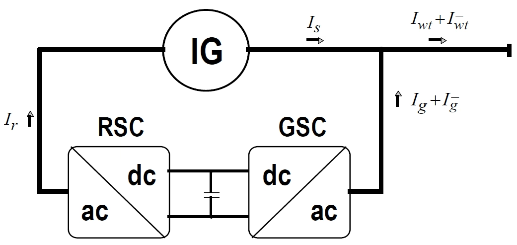
In the implemented method the grid-side converter is commanded to inject a compensating negative-sequence current, so that the total grid current contains the required sequence content while reducing the adverse effect on the DFIG. The objective is a combination: supporting the required grid-code negative-sequence behaviour, balancing the current drawn from the network, and reducing the dc-link \(2\omega\) ripple. The grid-side current then carries both sequence components:

\[ \underline{i}_g = \underline{i}_g^{+} + \underline{i}_g^{-} \]
\(\underline{i}_g\)
total grid-side converter current injected into the network
\(\underline{i}_g^{+}\)
positive-sequence component — the normal power transfer and support
\(\underline{i}_g^{-}\)
negative-sequence component — the compensation that counteracts the imbalance

The GSC actively shapes the grid-side current waveform, adding a negative-sequence part so the total current drawn from the network is balanced and the dc-link \(2\omega\) ripple is reduced. It can reduce the negative-sequence impact seen by the network and help stabilise the dc link, but it cannot remove all machine-side negative-sequence effects under every fault condition; the directly-connected stator is eased only indirectly, through the grid impedance.

Single-line diagram of DFIG negative-sequence compensation through the grid-side converter: the induction generator (IG) with its rotor-side converter (RSC) and grid-side converter (GSC) sharing a dc link, the grid current I_g split into positive- and negative-sequence parts, and the GSC injecting a calculated negative-sequence current so the total current drawn from the network stays balanced.
Figure 1 — Negative-sequence compensation through the GSC: the grid-side converter injects a negative-sequence current so the total grid current \(I_g=I_g^{+}+I_g^{-}\) supplies the network’s negative-sequence demand, balancing the current drawn from the network and reducing the dc-link \(2\omega\) ripple; the directly-connected induction-generator stator is eased only indirectly, through the grid impedance.

Section 7

The GSC current references

The reference currents split cleanly by sequence. The positive-sequence references are simply the normal control references; the negative-sequence references are set to the machine-side (wind-turbine) negative-sequence currents, so the GSC supplies what the network requires:

\[ i_{dg}^{+\prime} = i_{dg}', \quad i_{qg}^{+\prime} = i_{qg}', \qquad i_{dg}^{-\prime} = i_{dwt}^{-}, \quad i_{qg}^{-\prime} = i_{qwt}^{-} \]
\(i_{dg}^{+\prime},\ i_{qg}^{+\prime}\)
positive-sequence GSC current references — from the normal control (\(i_{dg}',i_{qg}'\))
\(i_{dg}^{-\prime},\ i_{qg}^{-\prime}\)
negative-sequence GSC current references — the compensation terms
\(i_{dwt}^{-},\ i_{qwt}^{-}\)
the wind-turbine (machine-side) negative-sequence currents the GSC must supply

Positive sequence is ordinary power transfer; the negative-sequence references are the compensation that cancels the imbalance, set to the negative-sequence current the machine side would otherwise impose on the network.

What “normal control” means for the GSC

In undisturbed operation the grid-side converter runs at unity power factor — its reactive reference is held at zero (\(i_{qg}^{+\prime}=0\)) and its whole job is to keep the dc-link voltage steady while passing the rotor power through. It only begins to supply positive-sequence reactive current when a voltage excursion demands it, because the rotor-side converter’s own reactive contribution can fall short: the induction generator absorbs reactive power, so the RSC may not be able to meet the grid-code demand alone. Dedicated LVRT- and HVRT-boost blocks add the extra GSC reactive current at low and at high voltage respectively, and it is on top of this positive-sequence duty that the negative-sequence references above are then imposed and revised for the converter limit.

Section 8

Revising the references: converter limits and FRT

Those reference values are not the final word. The controller revises them considering the converter current limit and the fault-ride-through requirement, because perfect compensation is rarely achievable: the converter has a finite current, thermal limits and protection constraints, so a severe unbalance can ask for more negative-sequence current than the GSC can deliver. The GSC has one finite current capability, and positive-sequence reactive support, active-power transfer and negative-sequence compensation all compete for that same current margin. The result is a three-way trade-off between the positive-sequence reactive current many grid codes require, the negative-sequence compensation, and the converter’s own limits.

Section 9

Fault ride-through comes first

Of those competing demands, one wins. The major limiting factor is the fault-ride-through requirement. During a fault, many grid codes prioritise positive-sequence reactive current for voltage support first; only the remaining converter reserve is available for the negative-sequence compensation. So the compensation is secondary to FRT: if they conflict, FRT takes the current and the negative-sequence compensation is reduced or, in the worst case, set aside. The more severe or closer the unbalanced fault, the larger both the negative-sequence voltage and the FRT reactive-current demand — so exactly when compensation is most wanted, the least current margin is available for it, and it weakens. This is the same priority discipline met on the fault-behaviour page — reactive support for the grid before oscillation suppression for the machine.

Order of precedence

Grid-code positive-sequence reactive current → converter and protection limits → then, with whatever reserve remains, the negative-sequence compensation.

Section 10

Not yet a common method

This remains a specialised implementation rather than a universal one, and it is honest to say so. It is complex: it needs reliable sequence extraction, fast control and a robust PLL, and it is sensitive to the same implementation details that govern sub-synchronous behaviour. Grid-code requirements for negative-sequence behaviour also vary by jurisdiction and continue to develop, so project studies should confirm the required negative-sequence behaviour with the OEM and the applicable grid-code requirements. In the model, the present implementation provides the structure and the GSC-based route.

Section 11

The stability connection: negative sequence and SSCI

There is a deeper reason to take the negative sequence seriously. Because the compensation changes the converter’s apparent sequence impedance, it can also affect weak-grid and SSCI behaviour: handling the sequences separately removes oscillatory components and shapes the negative-sequence impedance, so reducing the air-gap torque pulsation and improving converter–grid stability are two views of the same problem.

Section 12

Key points

Inject the negative sequence at the grid side — within the FRT budget

  1. A DFIG is exposed to negative sequence because its stator is directly grid-connected — more so than a Type-4 turbine decoupled by a full converter.

  2. Negative sequence can create a \(2\omega\) air-gap torque pulsation (and dc-link ripple) that adds cyclic mechanical stress to the drive train.

  3. RSC and GSC compensation act through different paths: the RSC acts more directly on the machine torque, while the GSC shapes the grid current and dc-link balance.

  4. FRT reactive-current priority limits the available compensation: positive-sequence reactive current comes first, and the compensation uses only the remaining current margin.

  5. The method depends on reliable sequence extraction, robust PLL behaviour and current-margin management, and it ties into impedance / SSCI stability.

For the surrounding control and the general DSC, see the DFIG converter control, GSC fault behaviour and DSC implementation guides.

References

References

  1. EMTP® Documentation and Application Notes. Powersys / EMTP®.
Built on EMTP® · Expert spotlight
Portrait of Henry Gras, Chief Operating Officer of PGSTech

Henry Gras

Chief Operating Officer, PGSTech · Montréal, Canada

Henry Gras delivers the EMTP® University course “EMT Simulation and Analysis of Large-Scale Power Systems with Renewables” and works daily with the tool this article is written around.

Henry is based in Montréal, where he is Chief Operating Officer of PGSTech, the company responsible for EMTP® engineering services, commercialisation and continuing software development. He holds a master’s degree from Polytechnique Montréal, where he worked on electrical-machine research, and previously completed an engineering degree at École Centrale de Lyon in France.

Readers who want a structured programme on EMT simulation of large-scale power systems with renewables will find his EMTP® University course an excellent next step.

Henry’s technical expertise covers electromagnetic transient simulation, renewable-energy integration, power-system modelling, electrical machines, protection and specialist transient studies including TRV, transformer energisation, ferroresonance, insulation coordination and power quality.

Thirty-Part Technical Series

EMTP® Renewable Energy Modelling

A thirty-part guide to modelling wind, PV and full-converter plant in EMTP® — sources and turbines, converter and plant control, sequence control under faults, protection, and weak-grid and SSCI stability.

Part 15 Reading now

DFIG Negative-Sequence Compensation via the GSC

Reducing oscillating air-gap torque under unbalance by compensating negative sequence through the GSC.

Series progress 15 of 30

