
Renewable Modelling · DSC Implementation

Decoupled Sequence Control Implementation in EMTP®

Four current loops, decoupled solver and sequence reference frames

Decoupled sequence control (DSC) extends the grid-side converter (GSC) current controller so positive- and negative-sequence currents can be regulated separately during unbalanced operation. The implementation keeps the outer control, the current limiter and the fault-ride-through (FRT) logic in place, and adds a decoupled solver that distributes the available converter current into positive- and negative-sequence dq references — sequence separation, four current references, current limiting and FRT priority, and how those references reach the inner current loops.

Reading time ≈ 20 min · Four current loops, decoupled solver & sequence frames

Decoupled sequence control (DSC) is a converter-control method that separates positive- and negative-sequence current regulation so the converter can manage unbalanced grid conditions more deliberately. The problem it addresses runs in a chain: an unbalanced voltage carries both positive and negative sequence; their interaction produces power oscillations at twice the fundamental frequency (\(2\omega\)); the active oscillations ripple the dc (direct-current) link and disturb the control; and DSC responds by splitting the current control into sequence channels so selected oscillating terms can be reduced. Concretely, the original dq (direct–quadrature) current-control structure is extended into positive- and negative-sequence dq channels, giving four scalar current-reference components instead of two. What follows is how EMTP® produces those four references and passes them to the inner current loops.

Abbreviations used on this page
DSCDecoupled sequence control
GSCGrid-side converter
d–qDirect / quadrature rotating frame
PIProportional–integral controller
PLLPhase-locked loop
\(2\omega\)Twice fundamental frequency (second harmonic)
\(+\,/\,-\)Positive- / negative-sequence quantities
\(i_{dg}^{+*}\)Current reference: \(d,q\) axes, \(g\) grid current, \(+/-\) sequence, \(*\) reference
\(P_{c2},\ P_{s2}\)Second-harmonic active-power terms
FRTFault ride-through
\(V_{dc}\)dc-link (dc-bus) voltage
LPFLow-pass filter
Idqdq current limiter
DSRFDouble synchronous reference frame
SSCISub-synchronous control interaction
ac / dcAlternating / direct current
EMTP®Electromagnetic Transients Program
EMTElectromagnetic transient (time domain)
Key idea
  1. Under unbalance the instantaneous powers gain second-harmonic terms (\(p=P_0+P_{c2}\cos 2\omega t+P_{s2}\sin 2\omega t\)); the active oscillating terms \(P_{c2},P_{s2}\) ripple the dc-link voltage and disturb the phase-locked loop (PLL) and the loops.
  2. Implemented DSC keeps the existing outer control, Idq limiter and FRT, and adds a decoupled solver that computes four current references (\(i_{dg}^{+*},\,i_{qg}^{+*},\,i_{dg}^{-*},\,i_{qg}^{-*}\)) so the average powers \(P_0,Q_0\) follow their targets and the active oscillating terms are suppressed as far as the converter current margin allows (ideally \(P_{c2}=P_{s2}=0\)).
  3. Under severe sags and swells the priority is the positive-sequence reactive current \(i_{qg}^{+}\) demanded by the grid code; only the converter reserve left after that mandatory duty is used to suppress \(P_{c2},P_{s2}\). In the present model this priority is built-in, though the architecture is open and editable.
  4. In implementation the negative-sequence frame rotates the opposite way (angle and speed ×−1, with the exact sign set by the chosen PLL and frame convention) so its quantities appear constant; cross-terms between the sequences must be filtered out and the PLL needs sequence-aware tracking — both developed under sequence extraction and SSCI.
Key terms used on this page
01Decoupled sequence control
Controlling positive- and negative-sequence currents in separate dq channels, on top of the usual GSC control.
02Positive sequence
The normal forward-rotating symmetrical component; handled in the normal rotating frame.
03Negative sequence
The reverse-rotating component present under unbalance; handled in an opposite-rotating frame.
04Second-harmonic terms
\(P_{c2},P_{s2},Q_{c2},Q_{s2}\): the \(2\omega\) oscillating parts of the instantaneous powers under unbalance.
05Decoupled solver
The block that turns the plant objectives into the four sequence current references.
06Sequence frame
A rotating frame aligned to one sequence; positive and negative use opposite rotation directions.
07Four current references
\(i_{dg}^{+*},i_{qg}^{+*},i_{dg}^{-*},i_{qg}^{-*}\): the positive- and negative-sequence d and q targets.
08Cross-terms
Contamination of one sequence’s controller by the other; must be filtered or compensated out.
09PLL under unbalance
Angle tracking is harder when negative sequence is present; a more advanced PLL is usually needed.
10Priority logic
The rule giving grid-code positive-sequence reactive current first, the reserve to oscillation suppression.
11Zero-reference DSC
A simplified mode with the negative-sequence current reference set to zero; it limits negative-sequence current but does not by itself give full ripple cancellation, which needs the solver to allocate references within the current limit.
12dc-link ripple
The \(2\omega\) oscillation in \(V_{dc}\) caused by the oscillating active power.

Section 1

From concept to implementation

DSC is not a separate, unrelated controller — it is an extension of the ordinary GSC control. The outer loops, the current limiter and the FRT logic all remain; only the single dq current loop is replaced by a sequence-split structure fed by a solver that computes the references. The rest of this page follows that implementation in order: how the sequences are separated, the four current references and what they must achieve, the decoupled solver that computes them, what current limiting and FRT priority impose on them, and how the finished references reach the inner current loops.

Reading the current-reference notation

The four references are written \(i_{dg}^{+*},\,i_{qg}^{+*},\,i_{dg}^{-*},\,i_{qg}^{-*}\). In this notation \(d\) and \(q\) are the dq-axis components; the subscript \(g\) denotes the grid-side converter (grid) current; the superscripts \(+\) and \(-\) mark positive- and negative-sequence; and \(*\) marks a reference (target) value. Two related symbols appear later: a prime (\(i_{dg}'\)) is the outer-loop current reference before the sequence split, and \(I^{\lim}\) — capital \(I\), used only for limits — is a current limit from the Idq (dq current) limiter. So \(i'\) is the pre-solver reference, \(*\) the final sequence reference to an inner loop, and \(I^{\lim}\) a limit.

Section 2

Power under unbalance

Under unbalance, instantaneous power can be separated into an average component and oscillating components at twice the fundamental frequency. The starting point is the instantaneous power the converter exchanges with the grid: these are local GSC quantities — measured at the converter terminals, not at the point of interconnection (POI) — and the sign convention here is that positive \(P\) and \(Q\) are injection from the converter into the grid. Both the instantaneous active power \(p(t)\) and reactive power \(q(t)\) acquire a constant (average) part and a pair of second-harmonic oscillating terms:

\[ p(t) = P_0 + P_{c2}\cos 2\omega t + P_{s2}\sin 2\omega t, \qquad q(t) = Q_0 + Q_{c2}\cos 2\omega t + Q_{s2}\sin 2\omega t \]
\(p(t),\ q(t)\)
instantaneous active and reactive power exchanged with the grid
\(P_0,\ Q_0\)
average (dc) values of the instantaneous active and reactive power
\(P_{c2},\ P_{s2}\)
cosine and sine coefficients of the second-harmonic active-power oscillation (each may be positive or negative)
\(Q_{c2},\ Q_{s2}\)
cosine and sine coefficients of the second-harmonic reactive-power oscillation
\(2\omega\)
twice the fundamental angular frequency

Under unbalance the power is no longer constant: a dc part plus an oscillatory part at \(2\omega\). The active oscillating terms \(P_{c2},P_{s2}\) are the ones DSC most directly targets, because they ripple the dc link; the reactive terms \(Q_{c2},Q_{s2}\) still matter for the ac side — they affect the current, voltage support and converter loading — so they are not simply ignored. The average \(P_0,Q_0\) the converter controls are local targets, while the plant controller regulates the POI quantities they feed.

Section 3

Why \(P_{c2},\ P_{s2}\) ripple the dc link

It is specifically the active oscillating terms \(P_{c2}\) and \(P_{s2}\) that ripple the dc-link voltage. The dc link wants steady power transfer — the source feeds power in, the grid side draws it out. The dc-link capacitor must absorb the instantaneous mismatch between the source-side power and the grid-side active power, so if the grid-side active power oscillates at \(2\omega\), the capacitor absorbs and releases that energy each half-cycle and the \(2\omega\) active-power oscillation becomes a \(2\omega\) ripple on \(V_{dc}\). Once \(V_{dc}\) ripples it also disturbs the outer and inner loops and the protection logic; the PLL is disturbed separately, by the negative-sequence voltage it must track (developed in the cross-terms and PLL section), so the disturbance is not confined to the ac side. The underlying cause is covered under GSC fault behaviour; for implementation it is enough that these active second-harmonic terms are the quantity DSC must act on.

Section 4

Four current references

The original dq current loop becomes four scalar channels: positive-sequence d-axis, positive-sequence q-axis, negative-sequence d-axis and negative-sequence q-axis. Traditional DSC computes these four references — chosen to do two jobs at once: hold the average powers at their targets, and drive the active oscillating terms towards zero so the dc-link ripple is suppressed:

\[ \big\{\, i_{dg}^{+*},\ i_{qg}^{+*},\ i_{dg}^{-*},\ i_{qg}^{-*} \,\big\} \;\Longrightarrow\; P_0=P_0^{*},\quad Q_0=Q_0^{*},\quad P_{c2}=P_{s2}=0 \]
\(i_{dg}^{+*},\ i_{qg}^{+*}\)
positive-sequence d- and q-axis current references
\(i_{dg}^{-*},\ i_{qg}^{-*}\)
negative-sequence d- and q-axis current references
\(P_0^{*},\ Q_0^{*}\)
target average active and reactive powers
\(P_{c2}=P_{s2}=0\)
the cancellation condition for the active oscillating terms

The right-hand side is the ideal target. A simplified implementation may instead set the negative-sequence current reference to zero, but full active-power ripple cancellation normally requires the decoupled solver to allocate positive- and negative-sequence references within the available converter current limit — so in practice \(P_{c2},P_{s2}\) are suppressed as far as the current margin allows, not always driven exactly to zero.

It helps to keep the textbook goal separate from what the present EMTP® model does today:

Table 1 — The full DSC concept versus the present implemented model.
AspectFull DSC conceptPresent implemented model
Negative-sequence current referenceNon-zero, computed by the solverSet to zero
Main objectiveAverage-power control and active-ripple (\(P_{c2},P_{s2}\)) suppressionLimit negative-sequence current; preserve the architecture for future extension
Active-power rippleSuppressed as far as the current margin allowsNot fully cancelled — only negative-sequence current is limited

Section 5

Why the current loop splits by sequence

In balanced, positive-sequence-only control a single dq controller suffices, because there is one rotating frame in which the quantities are steady. Negative sequence breaks that: in the positive-sequence frame the positive-sequence quantities are dc-like but the negative-sequence ones oscillate at \(2\omega\), and no single frame can hold both as constants at once. The implementation answer is two rotating frames — a positive-sequence frame that rotates with the grid positive sequence and a negative-sequence frame that rotates in the opposite direction — each carrying its own d- and q-axis current regulator, so each sequence is dc-like in its own frame and a PI can control it. That is where the four current references come from. These are four control channels inside the one grid-side converter, not four separate hardware converters. The table below summarises what else changes.

Table 2 — What changes when decoupled sequence control is enabled.
AspectWithout DSCWith DSC
Current-control channels2 (d, q)4 (\(d^{+},q^{+},d^{-},q^{-}\))
Reference frame(s)one positive-sequence framepositive- and negative-sequence frames
Extra blockdecoupled solver
PLL / sequence extractionstandardmore complex (sequence separation)

Section 6

The decoupled solver

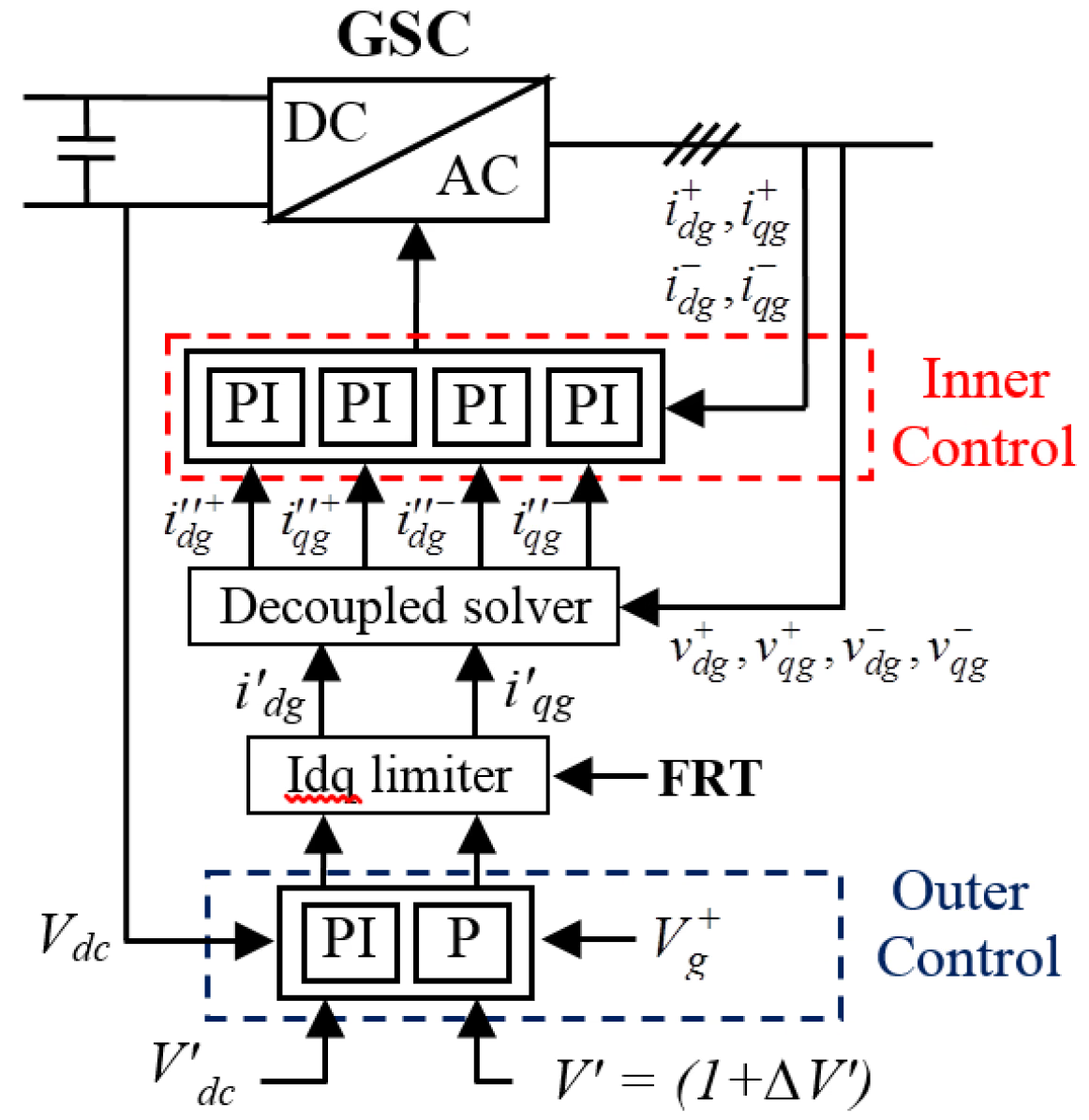
The new block in the diagram is the decoupled solver. It sits between the outer control / limiter and the four inner proportional–integral (PI) current regulators, and its job is to turn the plant objectives into the four sequence current references. It takes the desired positive-sequence active and reactive behaviour, the fault / FRT mode, the current limits and any desired negative-sequence behaviour, and solves for \(i_{dg}^{+*},i_{qg}^{+*},i_{dg}^{-*}\) and \(i_{qg}^{-*}\). This solver is where the current-allocation decision is actually made. In plain terms it allocates the available current between the positive- and negative-sequence components to satisfy the average-power targets and the ripple-suppression objective, subject to the current limits and the priority rules — a constrained allocation, not a black box — including how much margin is left for ripple suppression once the priority duties are met. In short, the solver maintains the average active- and reactive-power objectives while reducing the unwanted active-power oscillations, but only within the available converter current margin.

Schematic of the grid-side converter decoupled sequence control: the outer control and Idq (dq current) limiter with its FRT input feed a decoupled solver that produces four positive- and negative-sequence current references for four inner PI current loops, whose outputs are the converter dq voltage references realised by PWM or an average-value model.
Figure 1 — Grid-side converter decoupled sequence control. The outer control and Idq limiter (with the FRT input) feed a decoupled solver, which produces the four sequence current references \(i_{dg}^{+*},i_{qg}^{+*},i_{dg}^{-*},i_{qg}^{-*}\) for four inner PI current loops; their outputs are the converter dq voltage references, realised by PWM or an average-value model.

Section 7

What stays the same

It is worth stressing what DSC does not discard. The implemented DSC keeps the outer control and the Idq limiter to calculate \(i_{dg}',\,i_{qg}',\,I_{dg}^{\lim}\) and \(I_{qg}^{\lim}\) — the same outer dc-voltage and reactive / voltage control, the same current limiter, the same FRT logic and the same inner current-control idea. What changes is only what happens after the limiter: instead of the limited d- and q-references going straight to a single dq loop, they are passed into the decoupled-sequence block, which produces the positive- and negative-sequence references. DSC is an extension of the usual architecture, not a replacement for it — the current-loop structure underneath is the one you already know.

One subtlety worth flagging: the Idq limiter shown here acts on the positive-sequence outer references before the solver. Once the solver has produced four sequence references, the combined instantaneous phase current can exceed the converter rating even when each dq component looks acceptable, so a correct implementation must also enforce the total current limit on the combined reference — either as a final check after the solver, or as a constraint the solver itself applies. Whether that final limit is a separate block or built into the solver is model-specific and worth confirming for a given EMTP® model.

Section 8

Priority under severe sags and swells

This is where DSC meets fault ride-through. The converter has one finite current rating, and positive-sequence reactive support, active-current transfer and negative-sequence ripple suppression all compete for the same current capacity. During severe voltage sags and swells the current is limited, so the controller must decide what comes first. In normal operation the priority is the positive-sequence active current \(i_{dg}^{+}\), because the GSC must hold the dc-link voltage and export the source power. During a disturbance, many grid-code requirements prioritise the positive-sequence reactive current \(i_{qg}^{+}\) for voltage support — on an undervoltage (sag) the code typically requires reactive-current injection to raise the voltage, and on an overvoltage (swell) reactive-current absorption to lower it, so the sign of the reactive demand follows the disturbance. Negative-sequence compensation and second-harmonic ripple suppression are then secondary: they use only the converter current reserve that remains after the grid-code requirement has been met. That requirement and priority depend on the applicable grid code, the OEM model and the project settings — the present generic model uses a fixed priority, but that is not universal. If little margin is left, \(P_{c2}\) and \(P_{s2}\) are reduced only as far as that reserve allows.

FRT sets the priority; DSC distributes the rest

DSC cannot freely choose all four current components. The Idq limiter and FRT priority still decide what is physically allowed during the fault: satisfy the required positive-sequence reactive current first, then use whatever current capacity remains to reduce the second-harmonic oscillations as far as the margin allows.

Section 9

The priority is built into the present model

A natural question is whether the active / reactive priority can be set by hand. In the present generic model the priority is not a simple mask parameter: reactive-priority is embedded in the control blocks for the relevant fault mode, rather than exposed as a field you tick. It could be added as a parameter, but as delivered it is fixed logic. The saving grace is that the model uses an open control scheme — the user can open the controller block, inspect its internal logic and modify it, not only change the exposed mask parameters. So if a project needs a different priority, the structure is there to edit; the default is fixed, but it is not locked.

Section 10

The negative-sequence frame

Once the sequences are separated, the control is applied in two rotating frames. The positive sequence uses the normal rotating frame; the negative sequence uses the opposite rotation, so that its quantities also appear as steady (dc) values in their own frame. Put plainly, the negative-sequence controller uses the same angle magnitude but the opposite rotation direction. In implementation terms, the negative-sequence frame angle and speed are the positive-sequence ones with the sign reversed:

\[ \theta^{-} = -\,\theta^{+}, \qquad \omega^{-} = -\,\omega^{+} \]
\(\theta^{+},\ \omega^{+}\)
positive-sequence frame angle and speed (normal rotation)
\(\theta^{-},\ \omega^{-}\)
negative-sequence frame angle and speed (opposite rotation)

Reversing the sign makes the negative-sequence quantities steady in their own frame, which is what lets a PI regulator control them. The exact sign convention depends on the selected PLL and reference-frame convention — the principle is the opposite rotation, not a fixed −1 in every model.

Section 11

Cross-terms and the PLL

Two implementation realities make DSC harder than just adding loops. Cross-terms: when the sequences are extracted in controller coordinates they are not perfectly isolated, so transformations, compensation terms and filtering are needed to keep each sequence controller seeing mainly its own sequence. And the PLL must track angle under unbalance: the measured voltage contains negative sequence, which appears to a standard PLL as a \(2\omega\) oscillation and drives double-frequency ripple onto the estimated angle and frequency unless it is filtered or decoupled — so a sequence-aware PLL is usually required. How the extraction is actually built — the double synchronous reference frame (DSRF), the coupled feed-forward terms, the filter choices, their effect on the PLL, and the impact on sub-synchronous control interaction (SSCI) sensitivity — is developed in the dedicated DSC sequence extraction and SSCI article; here it is enough to know these two issues must be handled.

One point on where these operations sit is worth fixing now, because it shapes the whole implementation. The sequence dq control lives in the two rotating frames, but the feed-forward decoupling terms are kept in the stationary αβ (Clarke) frame rather than being duplicated inside each rotating frame. Keeping the decoupling in the stationary frame means it is written once and applied to the combined signal, so it does not have to be re-derived for the positive and negative frames separately — the Clarke transform moves the phase quantities into αβ, the Park transforms then resolve each sequence into its own dq axes, and the feed-forward correction is injected in αβ where both sequences coexist. In the EMTP® model this is why the Clarke and Park matrices both appear in the controller: the αβ stage is not merely an intermediate step but the frame in which the decoupling is actually enforced.

Section 12

Why DSC adds so much complexity

The cost of DSC over balanced control is the extra structure it stacks on the same outer objectives:

  • Sequence extraction — separating positive and negative sequence from the measurements.
  • Two rotating frames — a positive- and a negative-sequence frame, each with its own dq loops.
  • The decoupled solver — computing the four current references.
  • Current-limit allocation and priority logic — sharing the limited current between sequences and duties.
  • PLL and filter interaction — sequence-aware angle tracking and cross-term filtering.

That is why DSC is reserved for cases where unbalance, dc-link oscillation or sequence-specific grid-code current actually matter. A practical note: in the present model the structure is already built but the implemented version uses a zero negative-sequence current reference — the simplest mode. This limits negative-sequence current but does not by itself deliver full ripple cancellation; extending to controlled, non-zero negative-sequence references (allocated by the solver within the current limit) is the route to suppressing \(P_{c2},P_{s2}\) more completely. The hard part — the architecture — is already in place; the remaining work is mainly the reference logic.

Section 13

Key points

  1. Unbalance creates \(2\omega\) power oscillations; the active terms \(P_{c2},P_{s2}\) ripple the dc link.

  2. DSC splits the GSC current control into separate positive- and negative-sequence channels.

  3. A decoupled solver produces four dq current references (\(i_{dg}^{+*},i_{qg}^{+*},i_{dg}^{-*},i_{qg}^{-*}\)) to hold \(P_0,Q_0\) and suppress the active ripple.

  4. FRT priority and the current limit decide how much compensation is possible — positive-sequence reactive current first, ripple suppression only on the reserve.

  5. Severe faults may leave insufficient current margin for full ripple suppression; the present model uses a zero negative-sequence reference, with the architecture ready for controlled non-zero references.

References

References

  1. EMTP® Documentation and Application Notes. Powersys / EMTP®.
Built on EMTP® · Expert spotlight
Portrait of Henry Gras, Chief Operating Officer of PGSTech

Henry Gras

Chief Operating Officer, PGSTech · Montréal, Canada

Henry Gras delivers the EMTP® University course “EMT Simulation and Analysis of Large-Scale Power Systems with Renewables” and works daily with the tool this article is written around.

Henry is based in Montréal, where he is Chief Operating Officer of PGSTech, the company responsible for EMTP® engineering services, commercialisation and continuing software development. He holds a master’s degree from Polytechnique Montréal, where he worked on electrical-machine research, and previously completed an engineering degree at École Centrale de Lyon in France.

Readers who want a structured programme on EMT simulation of large-scale power systems with renewables will find his EMTP® University course an excellent next step.

Henry’s technical expertise covers electromagnetic transient simulation, renewable-energy integration, power-system modelling, electrical machines, protection and specialist transient studies including TRV, transformer energisation, ferroresonance, insulation coordination and power quality.

Thirty-Part Technical Series

EMTP® Renewable Energy Modelling

A thirty-part guide to modelling wind, PV and full-converter plant in EMTP® — sources and turbines, converter and plant control, sequence control under faults, protection, and weak-grid and SSCI stability.

Part 13 Reading now

Decoupled Sequence Control Implementation

Inside the controller — sequence separation, the four current references, the decoupled solver, current limiting and FRT priority.

Series progress 13 of 30

