
Renewable Modelling · Plant Controller

Plant-Controller Reactive Power Control in EMTP®: Q, V and PF Modes and Secondary Voltage Control

A wind or solar park does not leave reactive power to each turbine alone. Sitting above the fast converter loops is a plant controller — the wind-park controller (WPC) or PV plant controller (PPC) — that supervises active and reactive power at the point of interconnection (POI). It works on the secondary voltage control concept: the local converters act fast, and the plant controller trims their references more slowly so the whole plant meets a reactive-power (Q), voltage (V) or power-factor (PF) target. This guide shows how all three modes reduce to one common plant-level reactive-power loop, how the command reaches the local units (turbines or inverters), and why a simple proportional–integral (PI) regulator quietly compensates the collector grid’s own reactive effects.

Reading time ≈ 20 min · Q, V & PF reactive-control modes

Reactive power and voltage at the point of interconnection (POI) are a plant-level responsibility, not something each turbine or inverter settles for itself. Above the fast local converter controls sits a supervisory plant controller — the wind-park controller (WPC) on a wind park, the PV plant controller (PPC) on a PV park, identical in logic. It is a slower supervisory layer that watches the active and reactive power at the POI and trims the references handed to the local units so the whole plant meets the operator’s target. Its one central idea, which this guide develops, is that three operating modes — reactive power (Q), voltage (V) and power factor (PF) — all reduce to one common plant-level reactive-power loop.
Abbreviations used on this page
PPCPlant (park) controller
WPCWind-park controller
WT / WTCWind turbine / turbine controller
POIPoint of interconnection
PIProportional–integral controller
PFPower factor
\(Q,\ V\)Reactive power and voltage magnitude
\(I_q\)Quadrature (reactive) current
\(S\)Apparent power
EMTP®Electromagnetic Transients Program
EMTElectromagnetic transient (time domain)
RMSRoot-mean-square (phasor) simulation
dqDirect–quadrature rotating frame
ac / dcAlternating / direct current
\(P\)Active power
\(T_{com}\)Communication delay
\(\Delta U'\)Plant-wide reference correction
Key idea
  1. The plant controller is a secondary, supervisory loop. Primary control is the fast local converter (positive-sequence voltage or quadrature current); the PPC sits above it and regulates \(P\) and \(Q\) at the POI by sending reference corrections — it is a reference generator, not a fast actuator.
  2. All three modes funnel into one common plant-level Q-control PI. Q-control feeds the reactive reference \(Q'_{POI}\) directly; V-control converts a voltage error (an outer gain and limiter) into \(Q'_{POI}\); PF-control converts a power-factor target into \(Q'_{POI}\). The prime marks a reference or target; the unprimed value is the measurement.
  3. The PI’s integral action drives the measured POI reactive error to zero, so the converters absorb not only the requested reactive power but also the collector grid’s own reactive effects — provided the plant has enough reactive capability and the loop is not limited or disabled.
  4. The output is communicated and distributed to the units with a delay \(e^{-sT_{com}}\); in the aggregated model the many references collapse to one equivalent command. The reactive/voltage loop is prioritised, but the slower active-power loop still matters for ramp-rate, curtailment and frequency-response studies.
Key terms used on this page
01Primary control
The fast local converter loop, controlling positive-sequence voltage \(V_{pos}\) or quadrature current \(I_q\).
02Secondary voltage control
A slower plant-level loop that supervises \(P\) and \(Q\) at the POI and re-sets the primary references.
03Plant controller (PPC/WPC)
The supervisory controller that meets the reactive/voltage/power-factor target at the POI.
04Q-control mode
The POI reactive error \(Q'_{POI}-Q_{POI}\) drives a PI regulator directly.
05V-control mode
The POI voltage error is converted by an outer gain and limiter into a reactive-power reference.
06PF-control mode
The desired power factor is converted into a reactive-power reference using the measured active power, \(Q=\pm P\tan(\cos^{-1}PF)\).
07Reactive-power reference
\(Q'_{POI}\): the common target every mode produces before the common Q-control PI acts.
08Reference correction
\(\Delta U'\): the plant-wide voltage-reference correction the PI emits, distributed to the local units — not a direct reactive injection.
09Communication delay
\(e^{-sT_{com}}\): the transport lag as the command travels from the plant controller to the units.
10Aggregated command
In the aggregated model the many distributed references collapse to one equivalent control signal.
11POI error feedback
Working on the measured POI error lets the PI absorb internal plant reactive effects automatically.
12Apparent power \(S\)
\(\sqrt{P^2+Q^2}\) at the POI. Because \(S\) contains \(Q\), PF-control forms its reference from the measured active power \(P\) instead, avoiding a circular dependence.

Section 1

Two control levels: primary and secondary

Park reactive control is organised in two levels. At the primary level, the local converters control their own positive-sequence voltage \(V_{pos}\) or quadrature current \(I_q\) — the \(q\)-axis current component the converter uses, in its dq (direct–quadrature) reference frame, to produce reactive power or voltage support. This level is fast, local and per-unit. At the secondary level, the plant controller supervises the whole plant, regulating the active and reactive power measured at the POI. This split is the secondary voltage control concept borrowed from conventional power systems: fast local regulators do the electrical work, and a slower supervisory layer coordinates them toward a plant-level target. That is why the plant controller sends references rather than forcing reactive power into the network itself.

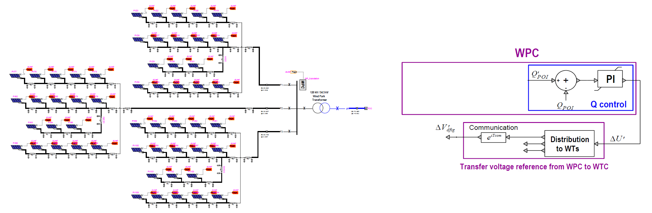
Schematic of the plant controller in context: the aggregated park with its turbines and inverters and collector network, the park transformer to the point of interconnection, and the WPC/PPC running the Q-control loop with its communication and distribution path back to the local units.
Figure 1 — The plant controller (WPC/PPC) in context: it measures active and reactive power at the POI, runs the secondary-level Q-control, and distributes a reference correction to the local units (turbines or inverters), whose primary-level converters do the fast regulation.

Section 2

The secondary voltage control concept

The mechanism is a simple supervisory cycle. The plant controller measures the plant’s behaviour at the POI, compares it with the requested target, and produces a plant-wide correction that is handed down to the converters, which change their own voltage or current to satisfy it. It then reads the POI again and repeats — a slow outer loop wrapped around the fast local ones.

Two timescales, by design

The converter inner loops react in milliseconds; the plant controller supervises more slowly. That separation is deliberate — the fast loops handle the electrical transient while the plant controller steers the steady operating point, so the two layers do not fight.

Section 3

Q-control mode

The simplest mode is direct reactive-power control. The operator or grid-side command gives a reactive-power reference at the POI, \(Q'_{POI}\); throughout this page a prime marks a reference or target, and the unprimed symbol is the measured value. The sign convention is the generator convention: positive \(Q\) is reactive power injected from the plant into the grid, negative \(Q\) is absorption. The plant controller measures the actual reactive power \(Q_{POI}\), forms the error \(Q'_{POI}-Q_{POI}\), and feeds it to a proportional–integral (PI) regulator. Standard closed-loop behaviour follows: if the injected \(Q\) is below target the error is positive, the PI raises its output, the local units are commanded to supply more reactive power, and the error shrinks.

\[ \Delta U' = K_p\,e_Q + K_i\!\int e_Q\,dt, \qquad e_Q = Q'_{POI} - Q_{POI} \]
\(e_Q\)
reactive-power error at the POI
\(Q'_{POI}\)
reactive-power reference (operator / grid-side command)
\(Q_{POI}\)
measured reactive power at the POI
\(K_p,\ K_i\)
proportional and integral gains of the regulator
\(\Delta U'\)
plant-wide voltage-reference correction sent to the local units (not a direct reactive injection)

A single PI acting on the POI reactive error — this is the common plant-level Q-control loop that V- and PF-control also feed.

Section 4

What the PI output actually is

It is worth being precise about what the PI emits. It does not switch or drive the converter. On the diagram it is a plant-wide voltage-reference correction \(\Delta U'\) — a small adjustment added to the voltage (or reactive) reference the local units already follow — distributed to the local turbine or inverter controls. The plant controller is a reference generator for the lower-level units, not the fast actuator that produces the current; the reactive power itself appears only when the local converters act on that corrected reference.

This also explains why the same plant objective can be met in two equivalent styles at the unit level, because reactive power and voltage are tightly coupled in an ac network. A local unit can follow a reactive-power reference (“inject this much \(Q\)”) or a voltage reference (“hold the terminal voltage near this target”), and it changes its reactive output accordingly — which is why the primary level is described as controlling \(V_{pos}\) or \(I_q\) while the secondary level supervises the plant objective.

Section 5

V-control mode

In voltage mode the starting quantity is a voltage reference at the POI, \(V'_{POI}\), rather than a reactive-power reference. The chain is short: the plant controller measures the actual voltage \(V_{POI}\), forms the voltage error \(V'_{POI}-V_{POI}\), scales it by a gain and applies a limiter, and the result is a reactive-power reference \(Q'_{POI}\). That reference then enters the same common Q-control PI as in Q-control mode — voltage mode does not send the voltage error straight to the converters.

\[ Q'_{POI} = \operatorname{lim}\!\Big[\,K_{Vpoi}\,(V'_{POI} - V_{POI})\,\Big] \]
\(Q'_{POI}\)
reactive-power reference fed to the common Q-control PI
\(V'_{POI}\)
voltage reference at the POI (operator command), in per unit
\(V_{POI}\)
measured POI voltage, in per unit
\(K_{Vpoi}\)
voltage-control gain: it converts the per-unit voltage error into a reactive-power reference, so its units are reactive power per unit voltage (e.g. Mvar per pu)
\(\operatorname{lim}[\cdot]\)
limiter that bounds the requested reactive power, keeping the demand within the plant’s converter/inverter capability

Voltage mode is therefore not a replacement for the Q loop but an extra step before it: an outer voltage loop that generates the reactive-power reference for the common Q-control PI.

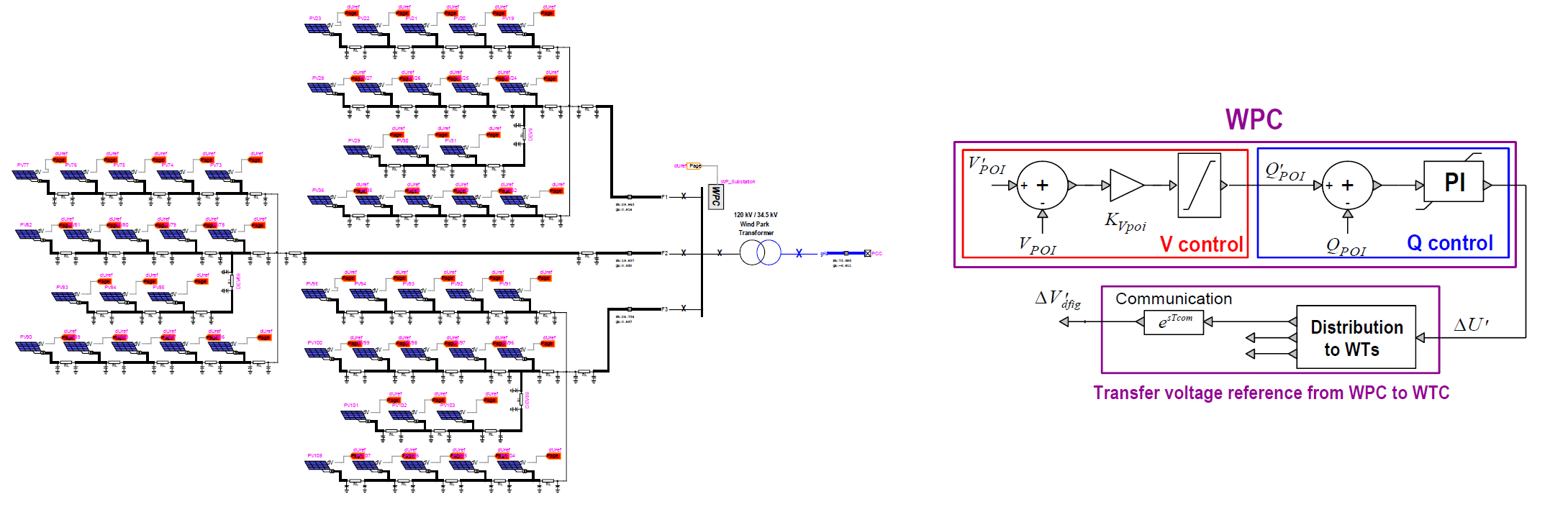
V-control mode block diagram: the POI voltage error passes through the gain K_Vpoi and a limiter to form a reactive-power reference, which feeds the common Q-control PI whose correction is distributed to the local units.
Figure 2 — V-control mode: the POI voltage error is scaled by the gain \(K_{Vpoi}\) and limited to form the reactive-power reference \(Q'_{POI}\), which then drives the common Q-control PI, whose correction is distributed to the local units.

Section 6

Why the outer voltage loop is just a gain and a limiter

It can seem surprising that the outer voltage control is only a gain and a limiter rather than a full regulator. The reason is a sensible division of labour: the common Q-control PI already provides the closed-loop tracking and the steady-state correction, so the outer loop does not need to duplicate that integration — it only has to turn a voltage deviation into a sensible reactive-power request, while the limiter keeps that request within reach. One caveat: this is the structure of this generic model. Real OEM or grid-code implementations often add more to the outer voltage path — droop, a deadband, measurement filters, extra PI action or a full Volt–VAR (Q–V) curve — so “just a gain and a limiter” is the teaching case, not a universal rule.

Section 7

PF-control mode

In power-factor mode the target is a desired power factor at the POI, \(PF'_{POI}\). A converter cannot act on “power factor” as a primitive control variable, so the plant controller first converts the PF target into a reactive-power reference and then uses the same common Q-control PI. Power factor is a ratio, so the conversion needs a magnitude and a sign. The magnitude comes from the plant’s active power: for a target \(PF'_{POI}=\cos\varphi\), the matching reactive power is \(Q=P\tan\varphi\). The sign — whether that \(Q\) is injected (lagging, over-excited) or absorbed (leading, under-excited) — is set by the operator’s leading/lagging selection, not by the number alone, because power factor is normally entered as a positive magnitude with a separate leading/lagging flag.

\[ Q'_{POI} = \pm\,P_{POI}\,\tan\!\big(\cos^{-1}\! PF'_{POI}\big) \]
\(Q'_{POI}\)
reactive-power reference fed to the common Q-control PI
\(PF'_{POI}=\cos\varphi\)
desired power-factor magnitude at the POI (a positive number, \(0\lt PF'_{POI}\le 1\))
\(P_{POI}\)
measured active power at the POI — using \(P\) rather than the apparent power keeps the conversion free of \(Q\)
\(\tan\!\big(\cos^{-1}PF'_{POI}\big)\)
the \(\tan\varphi\) implied by the target power factor
\(\pm\)
sign from the operator’s leading/lagging selection: \(+\) for lagging (\(Q\) injected), \(-\) for leading (\(Q\) absorbed)

Written with the measured active power \(P_{POI}\), the conversion has no circular dependence on \(Q\). The equivalent form \(|Q'_{POI}|=\sqrt{1-(PF'_{POI})^{2}}\;S_{POI}\) uses the apparent power instead; because \(S_{POI}\) contains \(Q\), that version leans on the closed loop to settle. Either way, once \(Q'_{POI}\) exists the common Q-control PI is identical.

PF-control mode block diagram: the target power factor is converted into a reactive-power reference (sign set by the leading/lagging selection), which feeds the common Q-control PI whose correction is distributed to the local units.
Figure 3 — PF-control mode: the target power factor is converted into a reactive-power reference \(Q'_{POI}=\pm P_{POI}\tan\varphi\), with the sign set by the leading/lagging selection.

Section 8

One common Q loop for every mode

Here is the unifying point. Whether the plant runs in Q-, V- or PF-control, it always comes back to the same common plant-level reactive-power loop. The modes differ only in how they produce the reference \(Q'_{POI}\); once that reference exists, the same Q-control PI and the same command distribution are used. That is the elegance of the design — it avoids building three separate plant-controller architectures, and it is why the Q-control block sits at the heart of every mode.
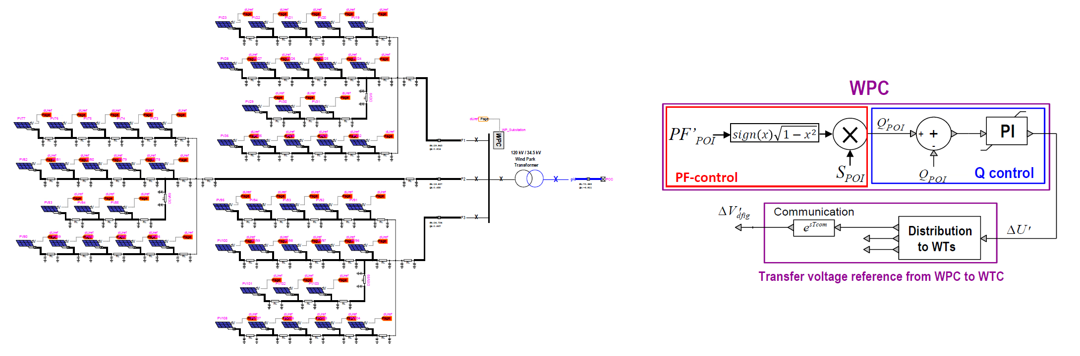
Table 1 — Each control mode takes a different operator target and forms the same reactive-power reference \(Q'_{POI}\); all three then drive the common plant-level Q-control PI, whose output is the plant-wide correction \(\Delta U'\) sent to the local units.
Control modeOperator targetHow \(Q'_{POI}\) is formedCommon loop output
Q-controlReactive power \(Q'_{POI}\)Used directly as the reference\(\Delta U'\) via the common Q-control PI
V-controlVoltage \(V'_{POI}\)Outer gain \(K_{Vpoi}\) and limiter on \((V'_{POI}-V_{POI})\)\(\Delta U'\) via the common Q-control PI
PF-controlPower factor \(PF'_{POI}\)\(\pm P_{POI}\tan(\cos^{-1}PF'_{POI})\), sign from leading/lagging\(\Delta U'\) via the common Q-control PI

Section 9

Communication and distribution

The plant controller is not physically inside each converter, so its output has to travel. On a wind park the corresponding block is labelled “transfer the voltage reference from the WPC to the WTC”; generically, the reference correction is communicated, passed through a delay \(e^{-sT_{com}}\), and distributed to the turbine or inverter units. That delay is real — plant-level communication is not instantaneous — and, together with the sampling rate of the plant controller, it shapes the dynamic response: too much lag slows the reactive/voltage support and can erode stability margins.

In a detailed plant many units receive their own adjusted references. In the aggregated EMT model, however, those similar units are represented by one equivalent block, so the distribution collapses to a single equivalent command. The control philosophy stays distributed and plant-level, but the implemented model compresses it into one effective control signal — a useful modelling distinction to keep in mind when reading the diagram against the model.

Section 10

How the PI compensates the collector grid

A natural question is whether the plant controller must account for the different impedances between the units and the POI when it allocates the reactive request — the collector cables, transformers and shunt elements all consume or produce some reactive power of their own. The answer is elegant: it does not hardcode any of that. It simply measures the actual POI response and closes a PI loop on the error.

So if the collector grid itself absorbs or supplies reactive power — cable charging, transformer reactance, shunt compensation — the plant controller sees the resulting POI error. If the units were commanded too little, \(Q_{POI}\) falls short of the target, the error persists, the PI output rises, the converter references increase, and the total converter output eventually compensates not only the requested POI reactive power but also the internal collector-grid reactive behaviour. The integral action is what makes this work: a purely proportional block would leave a steady-state error whenever there were internal losses or reactive effects, whereas the PI keeps pushing until the POI error reaches zero. This is why the answer to “what about the internal impedances?” is simply to point at the PI — with one condition. It works only while the plant has enough reactive capability and the loop is neither saturated at a limiter nor disabled; if the converters run out of reactive headroom, a steady POI error can remain despite the integral action.

The “disabled” case is deliberate and matters most during a severe POI voltage sag. A deep dip produces a large voltage error, which the slow reactive regulator would read as a demand for maximum reactive injection; left running, its integrator would wind up hard while the fault held the voltage down. When the fault then clears, that accumulated command would drive a burst of reactive power into an already recovering network and push the POI into overvoltage. To avoid this, the plant controller freezes the regulator once the sag crosses a severity threshold — its input is blocked so the output holds rather than integrating — and releases it as the voltage recovers. The freeze is a plant-level analogue of the local converter anti-windup: the detailed fault-ride-through logic, thresholds and release behaviour belong to the plant-controller implementation and FRT page.

Feedback over bookkeeping

Closing the loop on the measured POI error means the controller never needs an explicit term for the collector grid’s reactive consumption — the PI absorbs it automatically, as long as the plant has the reactive capability to supply it.

Section 11

The full control hierarchy

Putting the levels together gives the plant’s reactive-control hierarchy from the grid command down to the electrical action:

  1. Grid operator / dispatch. Requests a \(Q\), \(V\) or \(PF\) target at the POI.
  2. Plant controller (PPC/WPC). Measures the POI quantities and computes the plant-wide correction \(\Delta U'\).
  3. Communication / distribution. Transfers the plant command (with delay) to the local aggregated or individual converter controllers.
  4. Local converter control. Implements the actual reactive behaviour through local voltage or current control.

This page covers the first three levels — how the plant-level request is formed and dispatched — and stops at the plant-level reference. How that reference becomes a real change in \(I_q\), a local voltage reference, the modulation and the current-loop response inside the converter is the province of the converter’s own dq current control, covered in the grid-side converter current-loop and converter-control pages.

Section 12

Practical notes

  • The active-power loop is usually slower than the reactive/voltage support, because active dispatch follows scheduling, set-point moves, ramp rates and resource availability. Slower does not mean unimportant: it still matters for ramp-rate, curtailment, frequency-response and grid-code studies, where the active-power path has to be modelled too.
  • A requested \(Q\) is not always a delivered \(Q\). The actual reactive response is bounded by the converter/inverter current rating, voltage limits, the plant operating point and active-power output, transformer limits and grid-code priority — so the plant controller can ask for more than the plant can supply. This capability limit applies to both wind and PV parks.
  • Even when the plant controller requests a \(Q\) change, the local converter’s current limiter may reduce or re-prioritise it — especially during faults or at high active-power export, where current headroom is scarce. The fault-ride-through and anti-windup behaviour that governs this belongs to the plant-controller implementation and FRT page.
  • The same supervisory logic appears in RMS (phasor) tools as well as in EMTP®: an outer plant-level loop, a local inner loop, the Q/V/PF modes and error-based correction. What EMTP® adds is the faster electrical detail — converter switching or average-value behaviour, network asymmetry and initialisation — that the phasor representation cannot capture; the supervisory concept is the same, the electrical fidelity is not.
  • The plant controller forms the request; the converter executes it. It never forces reactive power into the network directly — it changes a reference, and the local converter current loop produces the electrical response.

Section 13

Key points

Three modes, one reactive-power loop

The plant controller is a secondary supervisory loop. Q-, V- and PF-control differ only in how they create the POI reactive-power reference; after that, one common plant-level Q-control PI sends a correction to the local units. The final electrical response still depends on converter capability, local current limits, communication delay and the selected sign convention. For the surrounding plant architecture, see the wind-park model and the PV-park model; for the mask settings, FRT and initialisation, the plant-controller implementation page.

References

References

  1. EMTP® Documentation and Application Notes. Powersys / EMTP®.
Built on EMTP® · Expert spotlight
Portrait of Henry Gras, Chief Operating Officer of PGSTech

Henry Gras

Chief Operating Officer, PGSTech · Montréal, Canada

Henry Gras delivers the EMTP® University course “EMT Simulation and Analysis of Large-Scale Power Systems with Renewables” and works daily with the tool this article is written around.

Henry is based in Montréal, where he is Chief Operating Officer of PGSTech, the company responsible for EMTP® engineering services, commercialisation and continuing software development. He holds a master’s degree from Polytechnique Montréal, where he worked on electrical-machine research, and previously completed an engineering degree at École Centrale de Lyon in France.

Readers who want a structured programme on EMT simulation of large-scale power systems with renewables will find his EMTP® University course an excellent next step.

Henry’s technical expertise covers electromagnetic transient simulation, renewable-energy integration, power-system modelling, electrical machines, protection and specialist transient studies including TRV, transformer energisation, ferroresonance, insulation coordination and power quality.

Thirty-Part Technical Series

EMTP® Renewable Energy Modelling

A thirty-part guide to modelling wind, PV and full-converter plant in EMTP® — sources and turbines, converter and plant control, sequence control under faults, protection, and weak-grid and SSCI stability.

Part 5 Reading now

Plant-Controller Reactive Power Control

Plant-level Q, V and power-factor modes and the secondary voltage control that coordinates the park.

Series progress 5 of 30


