EMTP® Lightning Studies

Transmission Line Tower Modelling for Lightning Studies in EMTP®

In a lightning study a tower is not just a grounding point — it is a surge-propagation structure. When lightning strikes the shield wire or tower top, the current travels down the tower as a wave, reflects from the footing impedance, and creates the voltage difference between tower and phase conductor that stresses the insulator string and can cause backflashover. This guide — part of the overhead-line modelling series — covers how the tower is represented in EMTP®: surge impedance for idealised shapes, equivalent radius, travel time, the simple, constant-, variable-impedance and multistorey models, ground-plane response, and how it all combines into insulator voltage.

Reading time ≈ 28 min · EMTP® lightning & towers guide

Transmission towers matter in lightning studies because they are part of the surge-current path between the shield wire, phase conductors, insulator strings, steelwork and grounding system. When lightning strikes a shield wire or tower top, the current does not vanish into the ground: it travels down the tower as a surge, reflects from the base and footing impedance, and creates voltage differences between the tower body and the phase conductors. Those differences appear across the insulator strings — and if the insulator voltage exceeds the withstand, backflashover follows. The tower model is therefore an electrical surge-propagation model, used to estimate tower-top, crossarm and insulator voltages and the effect of footing impedance — not merely a picture of a steel structure.
For lightning work the tower is represented with circuit elements — transmission-line sections, lumped inductances, resistances, crossarm stubs and grounding — rather than a full electromagnetic field model, capturing the dominant travelling-wave behaviour without modelling every steel member. This page sits alongside the overhead-line modelling page (which introduces shield wires, towers and footing) and the tower surge impedance and travelling waves page, and concentrates on the tower model itself.

Abbreviations used on this page
EMTP®Electromagnetic Transients Program
\(Z_T\)Tower surge impedance
\(R_E\)Tower footing / earth-electrode resistance
\(L_T\)Equivalent tower inductance
\(L_{GP}\)Ground-plane surge-response inductance
\(t_t\)Tower travel time
\(H_t\)Tower height
\(S_m\)Maximum lightning-current steepness
BFOBackflashover
EMTElectromagnetic transient
Key idea
  1. A tower is a surge-propagation structure, not just a grounding point: lightning current travels down it, reflects from the footing, and creates the tower–to–phase voltage that stresses the insulator.
  2. The controlling parameters are tower surge impedance, travel time, equivalent radius, height, crossarm geometry and footing impedance.
  3. Match the model to the study: a simple inductance for screening, a constant-impedance line for standard studies, a variable-impedance model for height-dependent voltage, and a multistorey model for detailed backflashover.
  4. Tower body and footing are modelled together: a low footing resistance does not remove the need for a tower surge model, because the early-time response is travelling-wave and ground-plane dominated.
Key terms used on this page
01Tower surge impedance, \(Z_T\)
The travelling-wave impedance seen by a fast surge going down the tower — set by tower geometry, not by the footing.
02Tower footing impedance, \(R_E\)
The impulse grounding impedance at the tower base; it controls the reflection that returns up the tower.
03Backflashover
Flashover from tower to phase across the insulator when the tower voltage rises far enough above the conductor.
04Travel time, \(t_t\)
Time for the surge to pass from tower top to base; it sets when base reflections return to the crossarms.
05Equivalent radius
A round-section radius matching a lattice tower’s geometry, so the round-conductor impedance formulas can be used.
06Constant-impedance model
The tower as one lossless line of a single surge impedance and travel time.
07Variable-impedance model
The tower as stacked sections of differing surge impedance, capturing internal reflections at geometry changes.
08Multistorey model
A sectioned tower with parallel R–L damping branches representing attenuation and early surge response.
09Ground-plane surge response
The early, partly inductive base reflection that differs from a simple lumped footing resistance.
10Crossarm stub
A short transmission-line section at a crossarm height, affecting the local insulator-attachment voltage.
11Insulator voltage
The phase-conductor voltage minus the tower voltage at that crossarm height — what drives flashover.
12Current steepness, \(S_m\)
The maximum rate of rise of the lightning current; it drives the inductive part of the tower voltage.

Section 1

Towers as surge-propagation structures

For simplified screening the tower may be a single surge impedance or an equivalent inductance; for detailed EMTP® studies it should be a constant- or variable-impedance transmission line, and in advanced cases a multistorey model with damping. The tower representation becomes especially important when a stroke terminates on the tower or shield wire, when backflashover is assessed, when footing resistance is low or moderate, when towers are tall or carry several voltage levels, when insulator voltages at different heights must be found, when crossarm geometry shapes the surge path, or when the tower voltage is a large part of the insulator stress.

Section 2

Tower surge impedance versus footing impedance

Tower surge impedance is the equivalent impedance seen by a fast surge travelling along the tower structure — a property of the tower body, not the ground. It is not the footing resistance, which is the impulse grounding resistance at the base. Picture the tower as a short vertical transmission line: a current wave enters at the top and travels down, and the geometry fixes the ratio of travelling voltage to current — the tower surge impedance. A high \(Z_T\) makes a given current produce a larger tower voltage; a low \(Z_T\) produces a smaller one. The footing impedance then sets the reflection at the base. In short, tower surge impedance controls the early travelling-wave voltage along the tower body, while footing impedance controls the reflection and the current injected into earth at the base.

What the insulator actually sees

The tower-top voltage depends on the lightning current magnitude and steepness, the tower surge impedance and travel time, the footing impedance, the crossarm geometry, the reflections between top and base, and the coupling between shield wires, tower and phase conductors. The insulator voltage is not the tower-top voltage — it is the difference between the phase-conductor voltage and the tower voltage at the height of the insulator attachment, which is exactly why detailed, sectioned tower models are useful.

Section 3

Tower voltage and backflashover

Backflashover occurs when the tower voltage rises far enough above the phase conductor to flash over the insulator string from tower to conductor — typically for strokes to the tower or shield wire. The early voltage contribution can be understood as a resistive plus an inductive term:

\[ V \approx I\,R_E + L_\text{eq}\,\frac{dI}{dt} \]
\(V\)
approximate tower voltage rise
\(I\)
lightning current
\(R_E\)
tower footing / earth-electrode resistance
\(L_\text{eq}\)
equivalent inductance of the tower and ground-plane response
\(dI/dt\)
lightning-current steepness

This is not a full tower model, but it makes the key point: a high footing resistance raises the resistive term, while a steep front raises the inductive term — so even a modest footing resistance can give a large insulator voltage under a very steep current. That is why tower modelling matters more for fast-front lightning than for slow overvoltages. Treat it as a screening interpretation only: a detailed EMTP® tower model represents the propagation delay, reflections and crossarm-level voltages explicitly.

Section 4

Tower model types — an overview

Tower models trade complexity for the effects they capture. A tower inductance is the simplest — good for preliminary or remote towers, but it represents no propagation delay or reflections. A constant-impedance transmission line represents the tower as a lossless line with one surge impedance and one travel time, capturing the basic travelling-wave behaviour. A variable-impedance transmission line divides the tower into sections each with its own surge impedance, better matching real geometry that narrows from base to top. A multistorey model adds parallel R–L damping branches between sections to represent attenuation and the ground-plane response — useful when accurate insulator voltages are needed across a range of footing resistances. A full electromagnetic or antenna-type model is reserved for validation and research, not routine studies. Whichever level is chosen, it should be consistent with the rest of the lightning study — a detailed tower model does not improve the result if the lightning-current waveform, footing model, insulator-flashover model or adjacent spans are oversimplified.

Section 5

Generalised tower surge impedance

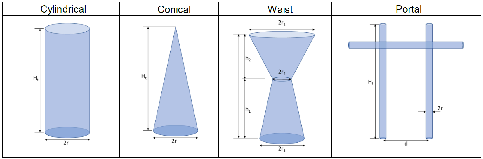
Tower surge impedance is estimated from idealised shapes — the classic cylindrical, conical, waist and portal forms set out by Sargent & Darveniza — because a geometrically complex tower can often be represented by an equivalent vertical structure (the travelling-wave derivation of \(Z_T\) is on the tower surge impedance page; here it is parameterised for the EMTP® tower model). With total height \(H_t\), equivalent radius \(r\) and \(c=3\times10^{8}\) m/s, the shape angle and the cylindrical and conical impedances are:

Four idealised tower shapes used to estimate tower surge impedance: cylindrical, conical, waist and portal (H-frame) structures.
Figure 1 — Idealised tower shapes — cylindrical, conical, waist and portal — used to estimate tower surge impedance. A real lattice tower is none of these exactly, but its dominant current path and overall geometry can usually be approximated by one of them.
\[ \theta=\tan^{-1}\!\left(\frac{r}{H_t}\right) \] \[ \text{cylindrical:}\ \ Z_T=60\left[\ln\!\left(2\sqrt{2}\,\frac{H_t}{r}\right)-1\right] \qquad \text{conical:}\ \ Z_T=60\ln\!\left(\cot\tfrac{\theta}{2}\right) \]
\(\theta\)
tower shape angle
\(r\)
equivalent tower radius, m
\(H_t\)
total tower height, m
\(Z_T\)
tower surge impedance, Ω

The conical form is the common practical approximation for tapered towers; the cylindrical form carries the extra \(-1\) and a \(\sqrt{2}\) factor — the same \(2\sqrt{2}\,H_t/r\) used in the portal leg \(Z_1\) below. For small \(\theta\), \(\cot(\theta/2)\to 2H_t/r\), so the conical impedance reduces to the familiar \(60\ln(2H_t/r)\) form. The shape angle \(\theta\) is dimensionless — keep a consistent radian/degree convention when transferring these formulas to a spreadsheet or script.

A waist-type tower (wider base and top, narrow middle) is reduced to a weighted average radius first:

\[ r_\text{av}=\frac{r_1 h_2 + r_2 H_t + r_3 h_1}{H_t} \qquad \theta=\tan^{-1}\!\left(\frac{r_\text{av}}{H_t}\right),\ \ Z_T=60\ln\!\left(\cot\tfrac{\theta}{2}\right) \]
\(r_\text{av}\)
weighted average tower radius
\(r_1,\ r_2,\ r_3\)
top, waist and base radii
\(h_1,\ h_2\)
base-to-waist and waist-to-top heights, \(H_t=h_1+h_2\)

A portal or H-frame behaves like two surge paths in parallel:

\[ Z_T=\frac{Z_1 Z_2}{Z_1+Z_2} \] \[ Z_1=60\left[\ln\!\left(\sqrt{2}\,\frac{2H_t}{r}\right)-1\right] \qquad Z_2=\frac{d\cdot 60\ln\!\left(\dfrac{2H_t}{r}\right)+H_t Z_1}{H_t+d} \]
\(Z_1,\ Z_2\)
the two equivalent impedance components
\(d\)
separation between the tower legs, m
\(r\)
equivalent leg radius, m

These idealised formulas estimate the first-order surge impedance and the dominant surge path; they are not exact descriptions of every member. Their purpose is a practical EMTP® tower representation.

Section 6

Equivalent radius for lattice towers

The impedance formulas assume round shapes, but real lattice towers are steel angles in rectangular or polygonal sections, so the cross-section is converted to an equivalent radius. For a rectangular section of width \(a\) and depth \(b\):

\[ r_\text{eq}=\frac{a+b}{\pi} \]
\(r_\text{eq}\)
equivalent radius, m
\(a,\ b\)
width and depth of the tower section, m

This is a simple perimeter-equivalent estimate, matching the rectangular perimeter to the circumference of a circle; an equal-area circle gives \(r=\sqrt{ab/\pi}\) instead, and the two differ unless \(a=b\). It is a practical approximation, not a detailed model of the lattice. Crossarms and tapering sections use the same idea. The point: do not use the physical leg radius as the tower radius unless the model really is one tubular member; for a lattice, use a radius that represents the overall current path.

Section 7

Tower travel time

The travel time is the time for a surge to pass from tower top to base:

\[ t_t=\frac{H_t}{c}\quad\text{(towers without crossarms)} \] \[ t_t=\frac{H_t}{0.85\,c}\quad\text{(towers with crossarms or lattice-path effects)} \]
\(t_t\)
tower travel time, s
\(H_t\)
tower height, m
\(c\)
speed of light, \(3\times10^{8}\) m/s

The \(0.85c\) form does not mean waves travel slower than light — it accounts for the longer, more complex effective path through a lattice with crossarms (reported values span \(0.7\text{–}0.9c\), with \(0.85c\) a common default). It is an empirical modelling approximation, not a material propagation velocity. The travel time matters because it sets when base reflections return to the top and crossarm levels and influence the insulator voltage during the critical early microseconds.

Section 8

Simple inductance and constant-impedance models

The simplest representation is an equivalent inductance:

\[ L_T=\frac{Z_T}{c}\,H_t = Z_T\,t_t \]
\(L_T\)
equivalent tower inductance, H
\(Z_T\)
tower surge impedance, Ω
\(H_t,\ t_t\)
tower height and travel time

Useful for hand calculations and screening, or for towers far from the strike where tower reflections barely matter. But it represents no travel time, no reflections and no crossarm-level voltages, so it must not be used where accurate insulator voltages are needed at the struck or adjacent towers. It suits short towers, a footing resistance that dominates the rise, remote towers, or preliminary screening.

A better choice is a constant-impedance lossless line defined by \(Z_T\), \(H_t\), \(t_t\) and the footing impedance: the surge travels down the tower and reflects from the base. It is practical and widely used where a single equivalent surge impedance is adequate. It cannot, however, give accurate voltages at different crossarm heights without added tapping points or sections, and it ignores the change of geometry from top to base — use a more detailed model when the geometry varies or when per-phase insulator voltages matter.

Section 9

Variable-impedance transmission-line model

A real tower is wider at the base and narrower above, with crossarms adding horizontal paths, so a more realistic model divides it into sections, each with its own surge impedance and travel time. For a round section of height \(h\) and equivalent radius \(r\):

\[ Z=60\,\cosh^{-1}\!\left(\frac{h}{r}\right)\ \approx\ 60\ln\!\left(\frac{2h}{r}\right)\ \ (h\gg r) \qquad t=\frac{l}{c} \]
\(Z\)
section surge impedance, Ω
\(h,\ r\)
section height and equivalent radius, m
\(t,\ l\)
section travel time and length
\(c\)
speed of light, \(3\times10^8\) m/s

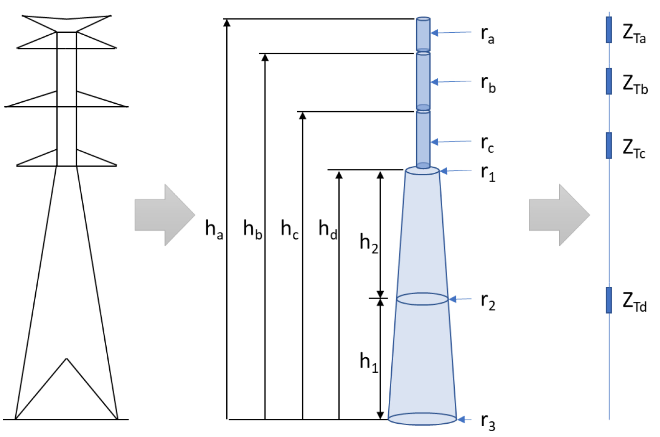
Here \(h\) is the section height above the ground reference and \(r\) its equivalent radius, and this is the lossless single-conductor surge impedance — not a multi-conductor matrix term. The same expression serves vertical sections and crossarms with a suitable equivalent radius. A variable-impedance model is more accurate than a constant-impedance one because it allows reflections and transmissions at geometry changes — and those internal reflections shape the crossarm-level voltages and hence the insulator stress.

Tower modelled as a variable-impedance transmission line: stacked vertical sections of differing surge impedance and travel time, with the footing impedance at the base.
Figure 2 — Tower represented as a variable-impedance transmission line. The tower is divided into vertical sections, each with its own equivalent radius, surge impedance and travel time, so internal reflections and the tower voltage at each phase-attachment height can be represented.

Section 10

Crossarms in tower models

Crossarms are short transmission-line stubs connected at the relevant height. Their influence is usually smaller than the main body and footing, but they shape the local voltage at the insulator-attachment point. Their surge impedance uses the same \(Z=60\cosh^{-1}(h/r)\approx60\ln(2h/r)\) expression, with \(h\) the crossarm length and \(r\) its equivalent radius. Crossarms also lengthen the apparent surge path, which is why a tower with crossarms is often given the effective \(0.85c\) propagation speed. Represent crossarms explicitly when insulator voltages at different phase levels are needed, when the crossarm geometry is wide, when several circuits share the tower, or when the study targets backflashover; for simpler studies they can be captured indirectly through the reduced propagation velocity. This crossarm impedance is approximate — it is used mainly to improve the local voltage at the insulator-attachment point, not to model every steel member.

Section 11

Ground-plane surge response

The base reflection is often modelled as a footing resistance, but measurements and field studies — the apparent ground-plane surge response described by Gutierrez et al. — show the early reflection from the tower base can differ from a simple lumped resistance — the initial response has an inductive character. It can be represented by an equivalent ground-plane inductance at the base:

\[ L_{GP}\approx 60\,t_t\ln\!\left(\frac{t_f}{t_t}\right) \]
\(L_{GP}\)
ground-plane surge-response inductance, H
\(t_t\)
tower travel time, s
\(t_f\)
lightning-current front time, s

Use this only when the front time exceeds the tower travel time, \(t_f>t_t\); if \(t_f\) is close to or smaller than \(t_t\) the approximation should not be used blindly. It captures the finite time for the surge to interact with the tower–ground system. It matters most when the footing resistance is low: a high footing resistance dominates the rise, but with low resistance the tower and ground-plane inductive effects become a larger part of the insulator voltage. A low footing resistance does not make the early-time tower voltage negligible under fast fronts.

Section 12

Multistorey tower model

The multistorey model (after Ishii et al., calibrated to measured UHV tower surge response) extends the variable-impedance model: each section has a surge impedance and travel time, and a parallel R–L branch is added to represent attenuation and damping, because a real lattice tower is not a perfectly lossless line. It was developed to reproduce measured tower surge response and is used where the voltage distribution along the height — and the insulator voltage at each level — must be accurate.

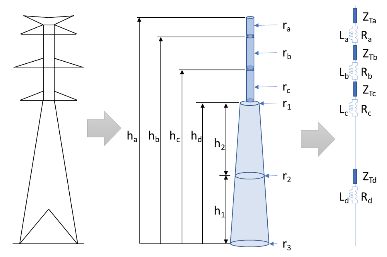
Multistorey tower surge-impedance model: several stacked surge-impedance sections each shunted by a parallel resistor-inductor damping branch, terminated by the tower footing impedance.
Figure 3 — Multistorey tower model: section surge impedances with parallel R–L damping branches that represent attenuation and the early surge response — used where insulator voltages at different heights are needed for detailed backflashover studies.
\[ R_{\text{damp},i}=\Delta R_i\,l_i \qquad L_i=2\tau R_{\text{damp},i},\ \ \tau=\frac{h_a}{c} \] \[ \Delta R_d=\frac{2Z_{Td}}{h_d}\ln\!\frac{1}{\alpha_d} \qquad \Delta R_i=\frac{2Z_{Ti}}{h_a-h_d}\ln\!\frac{1}{\alpha_i} \]
\(R_{\text{damp},i},\ L_i\)
damping resistance and inductance of section \(i\) — the subscript “damp” distinguishes it from the impulse footing resistance \(R_i\) used on the footing and backflashover pages
\(\Delta R_i,\ \Delta R_d\)
resistance per unit length, upper and base sections
\(Z_{Ti},\ Z_{Td}\)
surge impedance of section \(i\) and the base section
\(h_a,\ h_d,\ l_i\)
tower-top reference height, base-section height, section length
\(\alpha_i,\ \alpha_d\)
attenuation coefficients (typically \(\approx0.7\text{–}0.8\))
\(\tau\)
time constant \(h_a/c\)

The resistor attenuates the initial travelling-wave reflection; the inductor then reduces the resistor’s long-term effect after the first wave interaction, so the R–L branch acts mainly on the early transient. The attenuation coefficient (\(\approx0.7\text{–}0.8\) in the original Ishii model, higher only when tuned to measurements) should follow the adopted method or project guidance.

Section 13

When a detailed tower model is needed

Detail is not always necessary — it depends on whether the tower voltage is a major part of the insulator voltage. A practical indicator compares the tower’s inductive voltage with the resistive footing voltage:

\[ (L_T+L_{GP})\,S_m \;\ge\; I\,R_E \]
\(L_T,\ L_{GP}\)
tower and ground-plane inductances
\(S_m\)
maximum lightning-current steepness
\(I,\ R_E\)
lightning current and footing resistance

This is a practical screening indicator from CIGRE TB 839 (the CIGRE technical brochure on transmission-line lightning performance, aligned with IEEE Std 1243), not a universal equality: with \(S_m\) the maximum current steepness (A/s), the inductive voltage \((L_T+L_{GP})\,S_m\) is compared with the resistive footing drop \(I R_E\) (both in volts) — when the inductive term is comparable with or greater than the resistive one, the tower’s surge behaviour should not be ignored. As an order-of-magnitude screen only, \(L_T\) is around \(1\ \mu\text{H/m}\) (single-pole) or \(0.5\ \mu\text{H/m}\) (lattice); for any real study derive \(L_T=Z_T\,t_t\) from the chosen surge-impedance model, and near design limits use a physically based tower model.

Use a detailed model when the footing resistance is low or moderate, the front is steep, the tower is tall, the study targets backflashover, insulator voltages at different heights are needed, several circuits share the tower, the crossarm geometry is complex, or the result is sensitive to tower voltage. Simpler models suffice for preliminary work, remote towers, footing-dominated responses, or approximate lightning performance.

Section 14

Footing impedance and its interaction with the tower

The tower and footing models are not independent: the surge running down the tower reflects from the footing impedance, and that reflection travels back up to affect the shield-wire, crossarm and insulator voltages. A high footing resistance gives a strong tower-voltage rise and higher backflashover risk; a low footing resistance reduces the resistive rise, but the early transient is still shaped by tower surge impedance and ground-plane inductance.

Model them together

A constant footing resistance can be conservative but may miss the true early-time reflection; detailed studies may need frequency dependence, soil ionisation, nonlinear grounding or a ground-plane surge-response inductance — though, as on the HIFREQ soil and footing page, simplified soil ionisation should not be credited as a default favourable reduction; if used at all, treat it only as a clearly labelled, validated sensitivity case, because its time lag can make it non-conservative for backflashover. Tower surge impedance and footing impedance must be modelled together: improving footing resistance reduces backflashover risk but does not remove the need for a tower surge model in fast-front studies, because the early microsecond response is governed by travelling waves and reflections, not steady resistance.

Section 15

Insulator voltage

The voltage across an insulator string is the difference between the phase-conductor voltage and the tower voltage at the corresponding crossarm height:

\[ V_\text{ins}=\bigl\lvert V_{\text{tower,arm}}-V_\text{phase}\bigr\rvert \]
\(V_\text{ins}\)
insulator voltage (stress)
\(V_{\text{tower,arm}}\)
tower voltage at the crossarm / attachment height
\(V_\text{phase}\)
phase-conductor voltage at the insulator

For backflashover the tower voltage rises above the conductor, so the stressing voltage is the magnitude of the tower-minus-phase difference. Simple but central: if the model gives only tower-top voltage, it may misrepresent the voltage across lower phase insulators. In multicircuit or multi-voltage towers the strings sit at different heights, so a variable-impedance or multistorey model — which provides the tower voltage at each level — is the appropriate choice. This page stops at the insulator voltage \(V_\text{ins}\); whether that voltage actually produces a flashover is decided by the flashover model on the air-gap and insulator flashover modelling page.

Section 16

Practical workflow and pre-acceptance checks

A practical sequence: define the study objective (shielding failure, backflashover, incoming surge, arrester duty, insulation coordination or lightning performance); identify the current injection point (tower top, shield wire, midspan or phase conductor); select the tower representation (inductance for screening, constant-impedance for standard studies, variable-impedance for height-dependent voltage, multistorey for detailed backflashover); estimate the surge impedance from the best-fitting idealised shape, converting lattice geometry to an equivalent radius; compute the travel time (\(H_t/c\), or \(H_t/0.85c\) with crossarms); include the footing impedance at an appropriate level of detail; add crossarms or tapping points where per-height insulator voltages are needed; represent the few spans around the strike with phase conductors, shield wires, towers and grounding; run sensitivity checks; and document every assumption.

Before accepting the model, confirm:

  • The tower model and idealised shape suit the actual tower and the study objective.
  • The equivalent radius is derived from geometry, not guessed; tower height and crossarm levels are correct.
  • The travel time and surge impedance are physically plausible.
  • The footing impedance is represented consistently with the study.
  • The insulator voltage is taken at the correct attachment height.
  • The lightning current waveform and front steepness are appropriate, with enough adjacent spans.
  • Results are checked for sensitivity to tower model type, footing resistance and front time.
  • No unrealistic numerical oscillations arise from excessive segmentation or unsuitable line sections.

Section 17

Choosing the tower model

A simple inductance gives a quick tower-voltage estimate but no reflections or crossarm-level voltage; a constant-impedance line captures the basic travelling-wave behaviour for many standard studies; a variable-impedance line suits towers whose geometry changes with height; a multistorey model adds damping and is preferred where measured-like response or accurate per-level insulator voltages are needed, especially at low footing resistance; a field/antenna model is for research and validation. Use the simplest model that captures the controlling physics — not a complex model for appearance, and not a simple one when tower reflections and height-dependent insulator voltages control the result.

Main takeaway

Represent towers as surge-propagation structures, not grounding points: the current travels through the tower, reflects from the footing and creates the tower–to–phase voltage that sets insulator stress and backflashover probability. The key parameters are surge impedance, travel time, equivalent radius, height, crossarm geometry and footing impedance; the idealised cylindrical, conical, waist and portal formulas give practical first estimates, and lattice towers need an equivalent radius. Tower body and footing matter equally — a high footing resistance raises the voltage, but a low one does not remove the need for a tower surge model, because the early-time response is travelling-wave and ground-plane dominated. Choose the model by study objective, front steepness, geometry, footing impedance and the insulator-voltage accuracy you need: as simple as possible, but detailed enough to capture the controlling mechanism.

References

References

The standards, technical brochures, key papers and reference works behind this page.

  1. IEEE Std 1243-1997, IEEE Guide for Improving the Lightning Performance of Transmission Lines. New York, NY, USA: IEEE, 1997.
  2. CIGRE Working Group 33.01, Guide to Procedures for Estimating the Lightning Performance of Transmission Lines, Technical Brochure 63. Paris, France: CIGRE, 1991.
  3. CIGRE Working Group C4.23, Procedures for Estimating the Lightning Performance of Transmission Lines – New Aspects, Technical Brochure 839. Paris, France: CIGRE, 2021.
  4. M. A. Sargent and M. Darveniza, “Tower surge impedance,” IEEE Transactions on Power Apparatus and Systems, vol. PAS-88, no. 5, pp. 680–687, May 1969.
  5. M. Ishii, T. Kawamura, T. Kouno, E. Ohsaki, K. Shiokawa, K. Murotani, and T. Higuchi, “Multistory transmission tower model for lightning surge analysis,” IEEE Transactions on Power Delivery, vol. 6, no. 3, pp. 1327–1335, Jul. 1991.
  6. A. R. Hileman, Insulation Coordination for Power Systems. New York, NY, USA: Marcel Dekker, 1999.
  7. J. A. Martinez-Velasco, Ed., Power System Transients: Parameter Determination. Boca Raton, FL, USA: CRC Press, 2010.

Sixteen-Part Technical Series

EMTP® Line, Cable & Lightning Modelling

A sixteen-part guide spanning line and cable modelling, overhead-line physics, lightning, and the dielectric strength of external insulation.

Part 10 Reading now

Tower Modelling for Lightning in EMTP®

Tower surge impedance, travel time, and the multistorey and variable-impedance tower models for backflashover.

Series progress 10 of 16