Air-Gap Flashover · EMTP®

Air-Gap and Insulator Flashover Modelling in EMTP®

Air-gap modelling is needed whenever a study must decide whether an insulation gap, spark gap, arcing horn or insulator string flashes over during a transient overvoltage. In an overhead-line lightning study the stress on an insulator is not the phase voltage — it is the voltage difference between the conductor and the tower or crossarm at the same instant and the same height. If that voltage exceeds the gap’s withstand for long enough, the air breaks down and a conducting path forms. EMTP® can represent this at several levels of detail, from an ideal voltage-controlled switch to an integral voltage-time device to a full leader-development model. This guide explains each option, the physics behind it, and when each is the right choice for lightning and switching work.

Reading time ≈ 32 min · Air-gap & insulator flashover guide

In EMTP®, air-gap behaviour can be represented at different levels of detail, and the right choice depends on the purpose of the study, the available data, the voltage waveform, the gap length, and whether the engineer needs only a simplified flashover indication or a realistic breakdown-time calculation. Two practical approaches dominate: the simple EMTP® Air Gap device, based on an integral (disruptive-effect) criterion; and the advanced leader-type model in the EMTP® example file air_gap_leader.ecf, which can be copied into a project and adjusted for the required gap length and gap type. The simple model is easier to use when voltage-time or laboratory-derived parameters are available; the leader model is more appropriate for long air gaps and transmission-line lightning studies, where breakdown time depends strongly on the applied waveform, the gap length and the leader-development process.
Abbreviations used on this page
EMTP®Electromagnetic Transients Program
CFOCritical flashover voltage (50% flashover, U₅₀)
BILBasic lightning impulse insulation level
LPMLeader progression model
\(V_0,\ K,\ D\)Integral-device reference voltage, exponent, disruptive-effect threshold
\(k_g\)Gap factor (relative to a rod-plane gap)
\(E_0\)Critical leader-gradient parameter (kV/m or MV/m)
CWFCritical wavefront (time-to-crest of minimum strength)
\(T_b\)Breakdown (time-to-flashover) time
Key idea
  1. Air breakdown is time-dependent: a higher voltage for a short time can behave differently from a lower voltage held longer. Model the gap with a time-dependent criterion, not a single fixed threshold.
  2. Match the detail to the gap: open (observe overvoltage) → voltage-controlled switch (withstand screening) → integral Air Gap device (voltage-time) → leader model (long gaps, non-standard impulses).
  3. The integral device is empirical (\(V_0,K,D\) fitted to voltage-time data); the leader model (air_gap_leader.ecf: Length + Gtype) is physical — better for several-metre gaps and irregular lightning waveforms.
  4. After flashover an ideal closed switch is a flashover path, not an arc model — add an arc representation for reclosing, secondary-arc or arc-energy work.
Key terms used on this page
01Air gap / flashover
An air insulation distance between two electrodes; flashover is its complete breakdown into a conducting arc path.
02Disruptive-effect (integral) method
An empirical criterion: flashover when the time-integral of voltage-excess above a reference reaches a threshold \(D\).
03Volt-time characteristic
The relationship between applied voltage and the time it takes a gap to break down; higher voltage breaks down faster.
04Streamer
A weakly ionised filamentary discharge that propagates into the gap from the high-field electrode.
05Leader
A highly ionised, conductive channel that develops from the streamer region; bridging the gap with a leader causes flashover.
06Leader progression model (LPM)
A model that computes leader length over time from the gap voltage and gap geometry until the leader bridges the gap.
07Predischarge current
Current flowing during streamer/leader development; for long gaps it can distort the voltage actually applied to the gap.
08Critical flashover voltage (CFO)
The crest voltage giving a 50% probability of flashover for a given gap, waveform and polarity.
09Gap factor \(k_g\)
The ratio of a configuration’s flashover voltage to that of a rod-plane gap (\(k_g=1\)); up to ~1.9 for conductor-rod.
10Rod-plane / rod-rod
Standard test geometries; rod-plane has the lowest strength (reference), rod-rod has leaders from both ends.
11Critical wavefront (CWF)
The switching-impulse time-to-crest that gives the minimum flashover strength (the bottom of the U-curve).
12Arcing horn / spark gap
A protective air gap set to flash over before the main insulation, diverting the surge to a defined path.

Section 1

Why air-gap flashover has to be modelled

In a lightning or switching study, the question is rarely just “how high is the overvoltage?” — it is “does the insulation flash over?” For an overhead line, the voltage that stresses an insulator string is the difference between the phase-conductor voltage and the tower or crossarm voltage at the same instant and the same height. That difference can exceed the phase voltage by a large margin during a backflashover, and it differs from phase to phase and from one crossarm level to another because the tower voltage changes with height. If the stress exceeds the gap’s withstand for long enough, the air breaks down and a conducting path is created — changing the network and diverting the surge. Capturing whether, when and where that happens is the job of an air-gap model.

Section 2

Why air gaps need a special model

Air insulation does not behave like a fixed-voltage switch. A flashover does not occur simply because the voltage exceeds one constant value; the breakdown depends on gap length, electrode or insulator geometry, voltage polarity, wavefront shape, the time spent above the critical voltage, atmospheric conditions, and the development of corona, streamers and leaders. A higher voltage applied briefly can give a different result from a lower voltage applied longer — which is exactly why voltage-time curves, integration methods and leader-progression models exist. For a transient study the modelling question is therefore not only “did the voltage exceed the insulation level?” but “did it exceed the required level for long enough, with the correct waveform and geometry, for a discharge to develop across the gap?”

Section 3

The physical breakdown process

The breakdown of a long air gap is usually described in three stages. First, corona or streamer activity starts in the region of highest electric field — near an electrode, arcing horn, conductor hardware or tower structure. Second, streamers propagate into the gap; if the voltage stays high enough, the streamer region extends across it. Third, a leader — a far more ionised channel than the streamer region — develops and propagates. When the leader bridges the full gap (or leaders from opposite electrodes meet), the gap breaks down and an arc path forms. The breakdown time can be interpreted as the sum of these stages:

\[ T_b \approx t_p + T_s + T_L \]
\(T_b\)
breakdown (time-to-flashover) time
\(t_p\)
corona / streamer inception time
\(T_s\)
streamer propagation time
\(T_L\)
leader development time

The full decomposition is \(T_b=t_p+T_s+T_i+T_L+T_g\), with an ionizing-wave time \(T_i\) and a gas-heating time \(T_g\); Shindo and Suzuki measured \(T_g<0.1\,\mu\text{s}\) and folded \(T_i\) into \(T_L\), giving the three-term form above. In strongly non-uniform gaps the corona-inception voltage is well below the breakdown voltage, so the high rate of rise reaches inception almost at once and the corona-inception time \(t_p\) is small — the controlling issue becomes streamer and leader development under the actual voltage waveform. (Under fast lightning fronts the time-to-breakdown still depends strongly on the volt-time characteristic, so the front itself is not dismissed.) This is why a leader model suits non-standard waveforms better than a fixed-voltage switch.

Section 4

Air-gap modelling options in EMTP®

For transmission-line studies the gap can be represented in several ways, in increasing order of realism:

  • Open gap — leave the insulation open and only observe the voltage across it; useful when the objective is the overvoltage itself, with no flashover allowed.
  • Voltage-controlled switch — close when the gap voltage exceeds a specified withstand (e.g. the BIL); easy, but it ignores the time-dependence of breakdown.
  • Simple Air Gap device — an integral (disruptive-effect) criterion that accounts for both magnitude and duration above a reference level.
  • Leader-type model — the black-box model in air_gap_leader.ecf; the most physical option, suited to long gaps, non-standard impulses and detailed flashover studies.
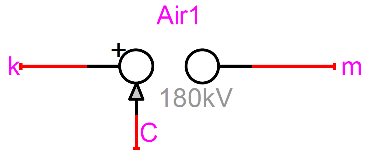
The EMTP Air Gap device symbol labelled Air1, with k and m terminals across the gap, a control pin C, a positive-polarity marker and a 180 kV label.
Figure 1 — The EMTP® Air Gap device (here “Air1”). The k and m terminals connect across the insulation; the control pin C can reset (re-open) the gap. Before flashover the device is an ideal open switch; once the integral criterion is met it becomes an ideal closed switch.

Section 5

The simple EMTP® Air Gap device

The simple Air Gap device represents the gap as an ideal open switch before flashover and an ideal closed switch after it. It is mainly intended for fast-front behaviour — spark gaps, arcing horns or a simplified insulator-flashover representation — and uses an integral (disruptive-effect) criterion — disruptive effect being the accumulated voltage-time stress above a reference voltage that leads to flashover:

\[ \int_{t_0}^{t}\left[\,v_{\text{gap}}(\tau)-V_0\,\right]^{K}\,d\tau \;\geq\; D \]
\(v_{\text{gap}}(\tau)\)
instantaneous voltage across the gap
\(V_0\)
minimum / reference voltage above which integration starts
\(K\)
exponent setting the sensitivity to voltage magnitude
\(D\)
disruptive-effect (integration) threshold
\(t_0\)
time at which \(v_{\text{gap}}\) first exceeds \(V_0\)

Integration starts only when \(v_{\text{gap}}\) exceeds \(V_0\); if the voltage falls back below \(V_0\) the integral is reset (the integrand is taken as zero, not negative, while \(v_{\text{gap}}<V_0\), and the accumulator hard-resets on each downward crossing). Flashover occurs when the accumulated integral reaches \(D\). The gap is an ideal open circuit before flashover and an ideal closed switch after; in EMTP® the control signal \(C\) can reset (re-open) the gap. This model is robust and convenient when \(V_0\), \(K\) and \(D\) are known from tests, manufacturer data or a validated voltage-time characteristic. Because it integrates voltage and duration above \(V_0\), it is more realistic than a pure voltage threshold.

Section 6

Meaning of the V₀, K and D parameters

\(V_0\) is the minimum voltage before the breakdown process is allowed to accumulate — a reference threshold for the integral, not necessarily the final flashover voltage. \(K\) is the exponent applied to the voltage excess above \(V_0\); a larger \(K\) makes the model more sensitive to high peaks. \(D\) is the disruptive-effect threshold; a larger \(D\) requires more voltage-time stress before flashover. These are normally fitted from voltage-time data, and the model relates directly to the gap’s voltage-time characteristic: a high voltage flashes over quickly, a lower voltage needs longer, and a voltage below the reference may not flash over at all. The example values below were derived (Rioual) for insulator strings fitted with spark gaps between roughly 0.28 and 0.80 m:

Table 1 — Example fitted Air Gap parameters for insulator strings with spark gaps (after Rioual, via the EMTP® device documentation), standard 1.2/50 µs lightning impulse. These values are examples for the stated arrangement and should not be transferred to other geometries, polarities or waveforms without validation.
Gap Spacing (m)KV0 (kV)D (kVK·µs)
0.800.923431.4×10−1
0.710.923111.3×10−1
0.610.932761.1×10−1
0.400.932056.9×10−2
0.350.931885.6×10−2
0.280.921673.7×10−2

Note how \(K\) stays close to 0.92–0.93 while \(V_0\) increases sub-linearly with gap length (roughly \(g^{0.7}\) across this set — \(343/167=2.05\) for a length ratio of \(2.86\)). \(D\) carries units of \(\text{kV}^{K}\!\cdot\mu\text{s}\), so its value is meaningless without them. These parameters should not be guessed or transferred outside the gap length, polarity and waveform range for which they were derived, and the exact digits should be confirmed against the EMTP® Air Gap / Rioual source before use.

Section 7

Limitations of the simple device

The simple Air Gap device is an empirical voltage-time model, not a physical leader model. It does not explicitly calculate streamer length, leader length, predischarge current or the distortion of the gap voltage by discharge current, and it normally behaves as an ideal switch after flashover unless an arc element is added. It suits simplified spark-gap studies, arcing-horn or protective-gap representation, screening studies, cases with available voltage-time data, or studies that need only the approximate flashover instant. It is less suitable for long air gaps of several metres, non-standard lightning waveforms, cases where leader-propagation time controls the result, cases where the voltage is strongly distorted by predischarge current, or studies that must represent the detailed flashover process. For those, the leader model is preferred.

Section 8

The advanced air-gap leader model

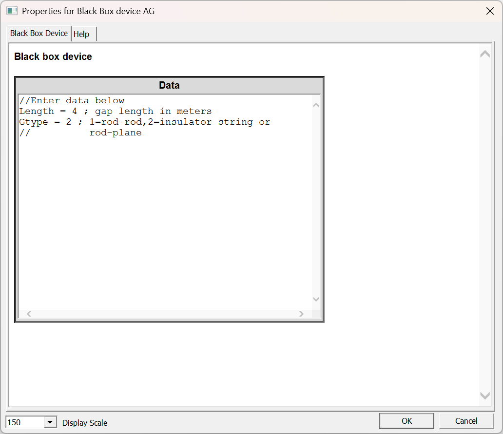
The advanced model in the EMTP® example file air_gap_leader.ecf represents the development of breakdown in long air gaps more realistically than the integral device. It is copied into the project and configured through just two inputs — the gap length and the gap type — while the applied surge is supplied by the external circuit; the model then computes whether breakdown occurs and at what time.

The EMTP black-box device data dialog for the air-gap leader model, showing two entries: Length = 4 (gap length in metres) and Gtype = 2 (1 = rod-rod, 2 = insulator string or rod-plane).
Figure 2 — Data for the air-gap leader (black-box) model. Only two inputs are set: Length (gap length in metres) and Gtype1 for a rod-rod gap, 2 for an insulator-string or rod-plane gap. The applied surge is supplied by the external circuit, and the model returns whether and when breakdown occurs.

Length is the air-gap length in metres. Gtype defines the configuration: Gtype = 1 for a rod-rod gap, and Gtype = 2 for an insulator-string or rod-plane gap. This matters because long gaps do not flash over to a fixed threshold — the discharge depends on how the leader develops during the applied impulse. The leader concept and the underlying physics are set out in the next two sections.

Section 9

The leader progression concept

A leader progression model (LPM) represents breakdown by calculating the extension of the leader channel across the gap. The widely used CIGRE form (used, for example, in the IEC 60071-2 / CIGRE worked examples) is:

\[ \frac{d\ell}{dt} = k_l\,v_{\text{gap}}(t)\left[\frac{v_{\text{gap}}(t)}{g-\ell} - E_0\right] \]
\(\ell\)
leader length (\(d\ell/dt\) = leader velocity)
\(v_{\text{gap}}(t)\)
instantaneous voltage across the gap
\(g\)
total gap length (\(g-\ell\) = remaining unbridged gap)
\(E_0\)
critical leader-gradient parameter of the air-gap model — not a universal air-breakdown field, and distinct from the soil-ionisation \(E_0\) used on the footing / HIFREQ page
\(k_l\)
leader coefficient (configuration, polarity, insulator type)

The leader advances only while the field in the remaining gap \(v_{\text{gap}}/(g-\ell)\) exceeds \(E_0\). As \(\ell\) grows, \(g-\ell\) shrinks and the field rises, so propagation accelerates; if the voltage falls too low, the leader stops and flashover may not occur. Because the model uses the actual time variation of the gap voltage, it can flash over on the tail of a lightning impulse — after the voltage peak — which a fixed-threshold switch cannot. Representative coefficients:

Table 2 — Leader-progression-model coefficients (CIGRE TB 63 / TB 72, after Table 2.11 in Martínez-Velasco).
ConfigurationPolaritykl (m2/V2/s)E0 (kV/m)
Air gaps, post & long-rod insulators+0.8×10−6600
1.0×10−6670
Cap-and-pin insulators+1.2×10−6520
1.3×10−6600

In the CIGRE / IEC backflashover worked example, an insulator-string leader coefficient \(k_l=1.3\times10^{-6}\ \text{m}^2/(\text{V}^2\,\text{s})\) and a mean critical gradient \(E_0\approx570\ \text{kV/m}\) are used. The LPM is the form implemented in many EMT line-flashover studies; the Shindo–Suzuki model below extends the idea to very long gaps where predischarge current matters.

Section 10

The Shindo–Suzuki long-gap leader model

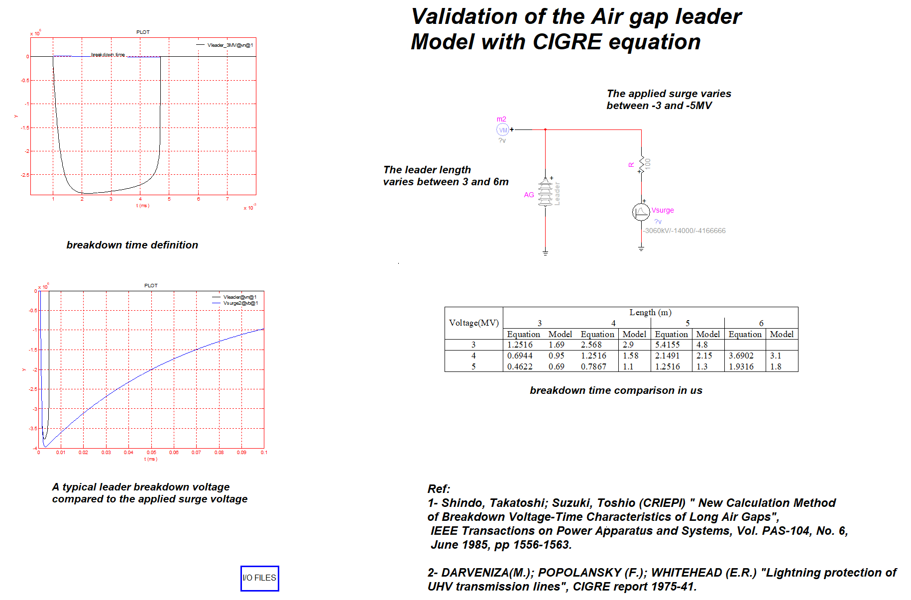
For long air gaps stressed by high lightning overvoltages, predischarge currents become significant (exceeding 1 kA) and distort the voltage actually applied across the gap. The Shindo–Suzuki model (IEEE PAS-104, 1985) is a more detailed long-gap leader model that accounts for this: it adds a predischarge-current term to the leader-velocity law above, with separate streamer-propagation-time and minimum-maintaining-voltage relations and configuration- and polarity-specific constants that are independent of the impulse waveform. It was validated against image-converter measurements for gaps up to about 7 m and both polarities. The full equation set is beyond this EMTP®-modelling overview — the practical point is that for several-metre gaps and irregular lightning waveforms a leader-development model is more defensible than a fixed threshold. More detailed leader formulations exist for specific gap geometries and waveforms; the EMTP® air_gap_leader.ecf implementation is validated against this approach:

Validation slide for the EMTP air-gap leader model: a breakdown-time definition plot, a leader breakdown voltage versus applied surge voltage plot, the AG/Vsurge test circuit, and a table comparing equation and model breakdown times for 3-5 MV surges and 3-6 m gaps.
Figure 3 — Validation of the EMTP® air-gap leader model against the CIGRE / Shindo–Suzuki equation. The applied surge is varied (−3 to −5 MV) and the gap (leader) length over 3–6 m; the table compares the analytical equation and the EMTP® model breakdown times (µs). Sources shown on the slide: Shindo & Suzuki, IEEE Trans. PAS-104, 1985; Darveniza, Popolansky & Whitehead, CIGRE report 1975-41.

Section 11

Integral device versus leader model

The two EMTP® methods ask different questions. The integral Air Gap device asks: has the voltage above \(V_0\) accumulated enough disruptive effect to cause flashover? — an empirical voltage-time test needing \(V_0\), \(K\) and \(D\). The leader model asks: has the streamer/leader process developed far enough to bridge the gap? — a physical (or semi-physical) test needing the gap length, gap type and the applied voltage waveform, with the internal equations computing the leader development and breakdown time. The integral device is easier to apply but only as good as its fitted parameters; the leader model is more physical but needs careful setup and validation against the intended gap type. Neither should be applied blindly.

Section 12

Strength data: gap factor and switching CFO

A voltage-controlled switch (or any fixed-threshold check) needs a withstand value, and the integral device’s \(V_0\) and \(D\) are ultimately calibrated against one. Those strength values come from the critical flashover voltage (CFO) and the gap factor \(k_g\) (a configuration’s strength relative to a rod-plane gap, \(k_g=1\)). For switching impulses the CFO follows gap-factor expressions such as Paris–Cortina (\(\mathrm{CFO}=500\,k_g\,S^{0.6}\)) and Gallet, with the U-curve, critical wavefront, polarity and statistical strength treated in full on the switching-surge dielectric-strength page. This page does not repeat that design procedure — it only notes where the model’s threshold values originate.

Section 13

Lightning-impulse CFO and volt-time

For lightning impulses the CFO follows similar gap-factor expressions (IEC 60071-2 gives \(\mathrm{CFO}^{+}=530\,S\,(0.74+0.26\,k_g)\) and \(\mathrm{CFO}^{-}=700\,S\)), and tower insulation is also described by a volt-time curve. The key point for a flashover model: for non-standard lightning impulses the required flashover voltage rises as the tail shortens (the \(\mathrm{CFO}_{NS}\) relation), so a single fixed CFO should not be used for strongly non-standard waves without care — one reason the leader model is preferred there. The full CFO, volt-time, BIL/BSL and non-standard treatment, with exact constants to check against the standard edition in use, is on the external-insulation dielectric-strength page.

Section 14

When to use the simple Air Gap device

Use the simple Air Gap device when the study is a simplified lightning study; the gap is a protective spark gap or arcing horn; the voltage-time characteristic is known; the gap is short or well represented by fitted \(V_0\), \(K\) and \(D\); only the approximate flashover timing is needed; or the flashover path can be treated as an ideal switch after breakdown. It is also useful for comparing different overvoltage cases quickly and consistently. The model is not universal, however: the same \(V_0\), \(K\) and \(D\) should not be transferred to a different gap length, electrode geometry, polarity or waveform without justification.

Section 15

When to use the advanced leader model

Use the leader model when the air gap is several metres long; the study concerns transmission-line insulator strings or long external clearances; the voltage waveform is non-standard; the front time is very short; the timing of breakdown affects the result; the voltage has multiple peaks or oscillations; or a more realistic flashover process is required. It is particularly useful for lightning studies where the calculated insulator overvoltage is not a clean standard impulse — natural lightning and travelling-wave reflections produce irregular waveforms with steep fronts, multiple peaks and short tails, for which a leader model is far better suited than a fixed-withstand switch. Copy air_gap_leader.ecf into the project and set the gap length and gap type for the case being studied.

Section 16

Air-gap flashover versus conductor corona

Air-gap flashover and conductor corona should not be confused. A conductor corona model represents distributed ionisation around an overhead-line conductor; it changes the travelling-wave velocity, attenuation and apparent capacitance along the line — it modifies the surge. An air-gap model represents insulation breakdown between two points (conductor and tower, arcing-horn gap, rod-plane gap or insulator string) and creates a conducting path after flashover — it changes the network topology. Both involve ionisation of air, but they are different models and are not interchangeable. (The APS note on the corona effect in EMTP® overhead lines covers the surge-modifying side.)

Section 17

Modelling the flashover path

When a gap flashes over, EMTP® normally represents it as a closed switch — acceptable if the study only needs to know that flashover occurred and how the surge is diverted. But an ideal closed switch is not a complete arc model: it does not represent arc resistance, arc elongation, extinction, reignition, secondary-arc behaviour or post-fault recovery. If the study concerns secondary arc, single-pole reclosing, arc extinction, post-flashover current or arc energy, a more detailed arc model is needed after the flashover event. For ordinary lightning-overvoltage studies the ideal-switch path is usually sufficient; for arc-duration or reclosing studies it is not.

Section 18

Practical EMTP® implementation workflow

A practical air-gap workflow runs:

  • Define the objective — overvoltage only, flashover detection, or post-flashover current.
  • Monitor the right voltage — the difference between the conductor and the tower/crossarm at the same height, not the phase voltage.
  • Choose the model — open gap, voltage-controlled switch, integral Air Gap device, or leader model, per Sections 14–15.
  • Set the gap length — the actual strike distance or effective insulation path, which may differ from the physical insulator-string length if the arcing path is different.
  • Set the gap type — for the leader model, the correct configuration (rod-rod, rod-plane or insulator string).
  • Apply a representative waveform — consistent with the objective; a standard test impulse is not always representative of the actual travelling-wave stress (see the lightning & switching waveform page).
  • Check flashover time and voltage — physically reasonable and consistent with gap length, polarity, waveform and model assumptions.
  • Run sensitivities — flashover can be sensitive to front time, polarity, gap length, model parameters and tower-footing response.

Section 19

Practical cautions

  • Do not use a fixed voltage threshold when the timing of breakdown is important.
  • Do not apply a simple Air Gap parameter set outside the gap length, polarity and waveform range for which it was derived.
  • Do not confuse the standard 1.2/50 µs test voltage with the actual non-standard voltage across a line insulator during a lightning event.
  • Do not use the leader model without checking that the selected gap type and length match the intended physical gap.
  • Do not assume flashover at one phase or crossarm represents all phases — tower voltage varies with height and each phase has a different instantaneous voltage.
  • Do not treat an ideal closed switch after flashover as an arc model — it is only a flashover path unless an arc model is added.

Section 20

Main takeaway

Match the model to the objective and keep it consistent with the waveform, gap length, polarity and monitored output. The integral Air Gap device is an empirical voltage-time model for calibrated, short or protective gaps; the leader model is a more physical representation for long gaps, insulator strings and the irregular lightning waveforms that travelling waves produce — neither should be applied blindly.

Suggested report wording

“The air insulation was represented using an EMTP® air-gap model appropriate to the purpose of the study. For simplified cases the EMTP® Air Gap device was used, applying an integral voltage-time criterion in which flashover occurs when the accumulated stress above a reference voltage reaches the disruptive-effect threshold; this is suitable where the required \(V_0\), \(K\) and \(D\) parameters are available or justified from voltage-time data. For long air gaps or non-standard lightning waveforms a leader-type model was used, which calculates the development of breakdown across the gap from the applied voltage waveform, the gap length and the gap configuration — more appropriate for insulator strings and external air clearances where the flashover time depends on streamer and leader development rather than a single fixed threshold. The advanced model was taken from the air_gap_leader.ecf example and adjusted for the required gap length and gap type. The voltage across the model was the actual insulation stress (conductor-to-tower/crossarm at the attachment point). After flashover the gap provides a conducting path; where arc extinction, secondary arc or reclosing performance was relevant, an additional arc representation was included.”

References

References

The standards, CIGRE technical brochures, the long-gap leader paper and the EMTP® software documentation behind this page.

  1. CIGRE Working Group 33.07, Guidelines for the Evaluation of the Dielectric Strength of External Insulation, Technical Brochure 72. Paris, France: CIGRE, 1992.
  2. CIGRE Working Group 33.01, Guide to Procedures for Estimating the Lightning Performance of Transmission Lines, Technical Brochure 63. Paris, France: CIGRE, 1991.
  3. IEC 60071-1:2019, Insulation Co-ordination – Part 1: Definitions, Principles and Rules. Geneva, Switzerland: International Electrotechnical Commission, 2019.
  4. IEC 60071-2:2023, Insulation Co-ordination – Part 2: Application Guidelines. Geneva, Switzerland: International Electrotechnical Commission, 2023.
  5. IEC 60060-1:2010, High-Voltage Test Techniques – Part 1: General Definitions and Test Requirements. Geneva, Switzerland: International Electrotechnical Commission, 2010.
  6. IEEE Std 4-2013, IEEE Standard for High-Voltage Testing Techniques. New York, NY, USA: IEEE, 2013.
  7. T. Shindo and T. Suzuki, “A new calculation method of breakdown voltage-time characteristics of long air gaps,” IEEE Transactions on Power Apparatus and Systems, vol. PAS-104, no. 6, pp. 1556–1563, Jun. 1985.
  8. A. R. Hileman, Insulation Coordination for Power Systems. New York, NY, USA: Marcel Dekker, 1999.
  9. J. A. Martinez-Velasco, Ed., Power System Transients: Parameter Determination. Boca Raton, FL, USA: CRC Press, 2010.
  10. EMTP® software documentation and built-in Help.

Sixteen-Part Technical Series

EMTP® Line, Cable & Lightning Modelling

A sixteen-part guide spanning line and cable modelling, overhead-line physics, lightning, and the dielectric strength of external insulation.

Part 14 Reading now

Air-Gap Modelling in EMTP®

Representing air-gap and insulator flashover — the integral Air Gap device and the leader model.

Series progress 14 of 16