
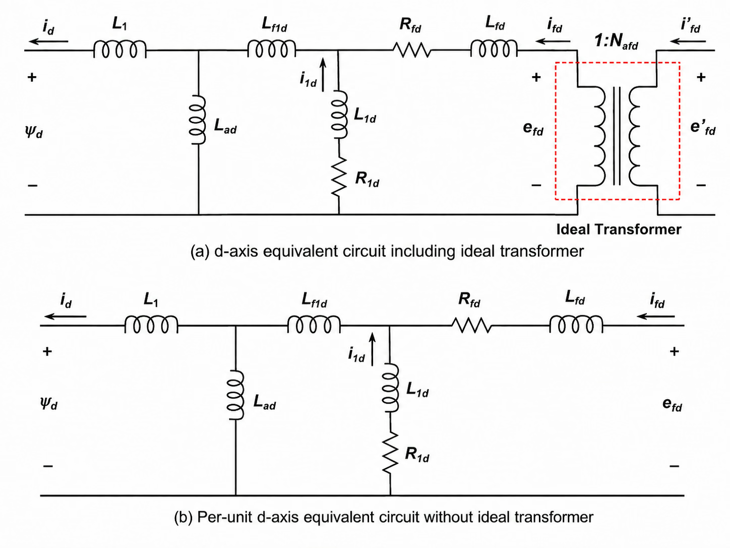
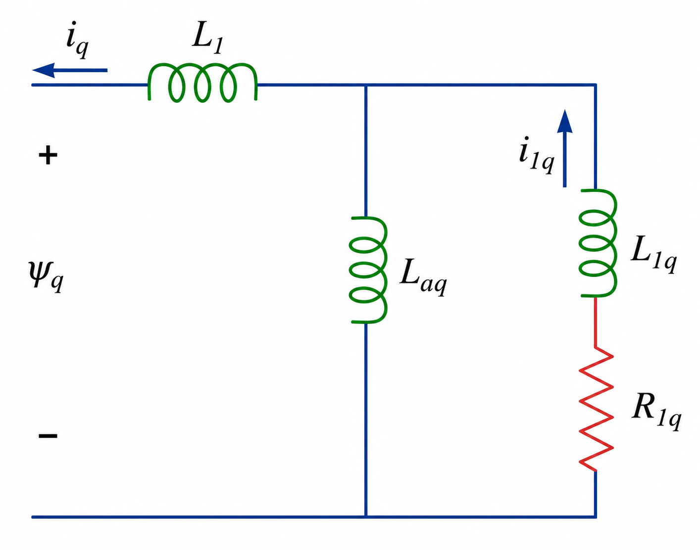
Per-unit scaling is especially useful for synchronous machines because, on the machine rating base, the impedances fall in a fairly narrow range — a fast engineering check. A reactance that looks odd in ohms may be perfectly normal in per unit, while a per-unit value far outside the expected range quickly flags a wrong voltage base, a wrong MVA base or a bad conversion. The aim here is a consistent set of equations in which the d-axis, q-axis, field and damper circuits can be represented by equivalent networks suitable for time-domain solution.



Per-Unit and Equivalent Circuits
Stator and rotor base quantities, the equal-air-gap-flux rotor referral, and the d- and q-axis equivalent circuits that the converted parameters populate.
Series progress
4 of 9