dq0 Reference Frame · EMTP®

Park Transformation and dq0 Representation of Synchronous Machines in EMTP®

In its physical form a synchronous machine has stationary stator windings and a rotating rotor, so the magnetic coupling between them — and therefore the inductances in the machine equations — changes continuously with rotor position. The equations are correct but time-varying, which makes them awkward to interpret and to solve. Park’s transformation fixes this by projecting the stator voltages, currents and flux linkages onto axes that rotate with the rotor: the direct, quadrature and zero-sequence axes. The result is the dq0 model — the bridge between the physical machine and the numerical machine model EMTP® solves in the time domain. This guide explains the transformation, the meaning of each component, the power-invariant form, and the simplified flux, voltage and torque equations it produces.

Reading time ≈ 34 min · The rotating-frame machine model

Park’s transformation does not remove the physics of the machine — it reorganises the same physics into a rotating reference frame where the main inductances become constant or much simpler. In an EMTP® study it is the bridge between the physical machine and the numerical model, letting the program represent the stator, field winding, damper windings, speed-voltage terms, electromagnetic torque and mechanical coupling in a form that solves efficiently in the time domain.

Abbreviations used on this page
EMTP®Electromagnetic Transients Program
dq0Direct / quadrature / zero-sequence axes
RMSRoot mean square
mmfMagnetomotive force
\(\mathbf{P}\)Park transformation matrix
\(\omega\)Rotor electrical angular speed (rad/s)
\(\theta\)Electrical rotor angle
F, D, Q1, Q2Field, d-damper, q-dampers
\(X_d, X_q\)d- and q-axis synchronous reactances
\(N_p\)Number of poles (\(N_p/2\) = pole pairs)
\(P_{\text{inst}}\)Instantaneous three-phase stator power
\(T_e\)Electromagnetic torque
Key idea
  1. In phase coordinates the stator inductances are time-varying functions of rotor angle — correct, but awkward to solve and interpret.
  2. Park’s transformation watches the stator from the rotor: three stationary phase quantities become a d-axis, a q-axis and a zero-sequence quantity, and the main inductances become constant.
  3. It is a change of variables, not an approximation: the inverse transformation recovers the exact phase quantities, provided one convention is used consistently.
  4. The payoff: diagonal stator inductances, axis-separated rotor coupling, a clean speed-voltage description and the compact torque \(T_e=\tfrac{N_p}{2}(\psi_d i_q-\psi_q i_d)\).
Key terms used on this page
01Park transformation
A change of variables projecting stator quantities onto rotor-aligned d, q and zero axes.
02Direct axis (d)
The rotor axis aligned with the field; \(i_d\) acts along the field-magnetising direction.
03Quadrature axis (q)
The rotor axis 90 electrical degrees from d; \(i_q\) is strongly torque-producing.
04Zero sequence (0)
The common component of the three phases; zero for balanced operation, no rotor coupling.
05Power-invariant form
A transformation choice preserving instantaneous three-phase power directly in dq0 variables.
06Speed voltage
The \(\omega\psi\) cross-coupling terms induced by the rotating reference frame.
07Reciprocity
Equal mutual inductances in both directions; guaranteed by the power-invariant scaling.
08Reluctance torque
Torque from the \(L_d\neq L_q\) difference in salient-pole machines.
09Pole pairs (Np/2)
Half the number of poles \(N_p\); the factor relating electrical and mechanical angle in the torque and speed equations.
10Subtransient response
The fast early response carried by damper currents, visible directly in the dq variables.

Section 1

Why phase-domain equations are difficult

In the physical machine the stator has three stationary windings — phases a, b, c — while the rotor carries the field winding (aligned with the direct axis) and damper windings. The magnetic coupling between a stator phase and a rotor winding depends on rotor position: when the d-axis aligns with phase a the phase-a–field coupling is maximum; 90 electrical degrees later it is zero; further on it reverses sign. The stator-to-rotor mutual inductance is therefore a sinusoidal function of rotor angle, and the stator self- and mutual inductances vary too because the effective air-gap permeance changes as the rotor moves. In phase coordinates the flux-linkage equation is:

\[ \begin{bmatrix}\boldsymbol{\psi}_s \\ \boldsymbol{\psi}_r\end{bmatrix} = \begin{bmatrix}\mathbf{L}_{ss}(\theta) & \mathbf{L}_{sr}(\theta) \\ \mathbf{L}_{rs}(\theta) & \mathbf{L}_{rr}\end{bmatrix}\begin{bmatrix}\boldsymbol{i}_s \\ \boldsymbol{i}_r\end{bmatrix} \]
\(\boldsymbol{\psi}_s,\ \boldsymbol{\psi}_r\)
stator and rotor flux-linkage vectors
\(\boldsymbol{i}_s,\ \boldsymbol{i}_r\)
stator and rotor current vectors
\(\mathbf{L}_{ss}(\theta),\ \mathbf{L}_{sr}(\theta),\ \mathbf{L}_{rs}(\theta)\)
stator and stator-rotor inductance matrices, dependent on rotor angle
\(\mathbf{L}_{rr}\)
rotor-rotor inductance matrix (constant in the classical form)
\(\theta\)
electrical rotor angle

The dependence on \(\theta\) is the difficulty: if the rotor is moving, the inductance matrix changes with time. A numerical program can solve time-varying equations, but the phase-domain form is hard to interpret and inefficient to solve. Park’s transformation removes this time-varying appearance from the stator equations by expressing the stator quantities in a rotating reference frame.

Section 2

The physical idea of Park transformation

Park’s transformation replaces the three stator phase quantities with a direct-axis component (aligned with the rotor field axis), a quadrature-axis component (90 electrical degrees from the d-axis) and a zero-sequence component (the common part of the three phases). The d- and q-axes rotate with the rotor — that is the key idea. Instead of watching the stator from the stationary phase windings, the model watches it from the rotor’s point of view, so the field winding, damper windings and the transformed stator d/q windings are all aligned with the same magnetic axes.

In one sentence

Park’s transformation converts three stationary stator quantities into two rotating magnetic-axis quantities (d and q) plus one zero-sequence quantity. For balanced three-phase operation the zero-sequence component is zero; for unbalanced faults, neutral displacement or ground-fault conditions it can become important, depending on the stator connection and grounding.

Section 3

Transforming the stator quantities

The transformation relates the phase vector and the dq0 vector through the Park matrix \(\mathbf{P}\). The same structure applies to stator voltage, current or flux linkage:

\[ \boldsymbol{f}_s = \mathbf{P}\,\boldsymbol{f}_{dq0} \qquad\qquad \boldsymbol{f}_{dq0} = \mathbf{P}^{-1}\boldsymbol{f}_s \] \[ \boldsymbol{f}_s = \begin{bmatrix}f_a \\ f_b \\ f_c\end{bmatrix} \qquad \boldsymbol{f}_{dq0} = \begin{bmatrix}f_d \\ f_q \\ f_0\end{bmatrix} \]
\(\boldsymbol{f}_s\)
vector of stator phase quantities — \(f_a, f_b, f_c\) for phases a, b, c, where \(f\) is the voltage \(v\), current \(i\) or flux linkage \(\psi\)
\(\boldsymbol{f}_{dq0}\)
transformed components \(f_d\) (direct axis), \(f_q\) (quadrature axis) and \(f_0\) (zero sequence)
\(\mathbf{P}\)
Park transformation matrix; \(\theta\) is the electrical rotor angle it uses

Because the inverse transformation reconstructs the actual phase quantities from the dq0 solution, the dq0 model is not an approximation — it is a change of variables. Used consistently for all quantities, it always allows the physical phase voltages and currents to be recovered.

Section 4

Meaning of the d, q and zero-sequence components

Direct-axis component

The d-axis component is the part of a stator quantity aligned with the rotor field axis. \(i_d\) is the stator current producing magnetomotive force along the direct axis — it interacts strongly with the field and d-axis damper winding; \(\psi_d\) and \(v_d\) are the d-axis flux linkage and voltage. The d-axis governs field-winding interaction, excitation response and direct-axis transient/subtransient behaviour, so it is usually central to fault current, field current and voltage recovery.

Quadrature-axis component

The q-axis component is aligned with the quadrature axis. \(i_q\) produces mmf along the q-axis and interacts with the q-axis dampers; \(\psi_q\) and \(v_q\) are the q-axis flux linkage and voltage. The q-axis is important for torque production, q-axis transient behaviour and salient-pole effects. Loosely, \(i_q\) is associated with torque-producing current and \(i_d\) with field-axis magnetising or demagnetising effect — the exact reading depends on the sign convention, but the axis separation is always useful.

Zero-sequence component

The zero-sequence component is the common part of the three phases — not a third rotating magnetic axis like d and q, but the common-mode component of the phase set. For a balanced set the phase quantities sum to zero:

\[ f_a + f_b + f_c = 0 \;\;\Rightarrow\;\; f_0 = 0 \]

In the classical dq0 model the zero-sequence winding has no magnetic coupling with the rotor circuits, because the zero-sequence stator mmf does not create the rotating air-gap field that links the rotor d- and q-axis circuits. Practical implication: under balanced conditions the zero-sequence equation can often be ignored; under ground-fault, open-phase or neutral studies it must be treated correctly, and its response depends strongly on the stator connection and grounding (a grounded-wye machine behaves differently from an isolated-wye or delta machine).

Section 5

Transformation constants and power invariance

The transformation carries scaling constants \(k_d,\ k_q,\ k_0\). Their values can be chosen in different ways; the choice does not change the physical machine if every quantity is transformed consistently, but it changes the numerical scaling and the form of the power and torque equations. One classical choice makes the peak transformed d/q currents equal the peak phase current. Another makes the transformation power-invariant — preserving instantaneous three-phase power directly — which avoids extra scaling factors in energy relations. A common power-invariant set is:

\[ k_d = \sqrt{\tfrac{2}{3}} \qquad k_q = \sqrt{\tfrac{2}{3}} \qquad k_0 = \sqrt{\tfrac{1}{3}} \]
\(k_d\)
d-axis scaling constant
\(k_q\)
q-axis scaling constant
\(k_0\)
zero-sequence scaling constant

With this choice the transformation is orthogonal and the transformed mutual inductances become reciprocal — a major numerical advantage, because it keeps the transformed inductance matrix symmetric where reciprocity is expected.

A transformation is power-invariant when the instantaneous stator power is the same in both frames:

\[ P_{\text{inst}} = v_a i_a + v_b i_b + v_c i_c = \boldsymbol{v}_s^{T}\boldsymbol{i}_s = \boldsymbol{v}_{dq0}^{T}\boldsymbol{i}_{dq0} = v_d i_d + v_q i_q + v_0 i_0 \]
\(P_{\text{inst}}\)
instantaneous three-phase stator power
\(v_a, v_b, v_c;\ i_a, i_b, i_c\)
phase stator voltages and currents
\(v_d, v_q, v_0;\ i_d, i_q, i_0\)
dq0 stator voltages and currents

A non-power-invariant transformation is not wrong, but it introduces extra numerical factors in the power expression and makes interpretation less direct. The essential rule is consistency: use the same convention for voltages, currents, flux linkages, torque and power — mixing conventions is a serious modelling error.

Section 6

The q-axis leading or lagging convention

References differ on whether the q-axis leads or lags the d-axis. The sign of \(k_q\) and of the speed-voltage terms depends on this choice, and it affects the signs of \(v_q\), \(i_q\), torque and power. This is not a trivial detail: comparing results from two programs that both use dq variables but define the q-axis differently can show apparently opposite signs even though the physical solution is identical. When comparing EMTP® results with textbooks, manufacturer data or another tool, check the axis convention first. For a report it is usually enough that the model is internally consistent and that any external comparison uses the same convention or is converted carefully.

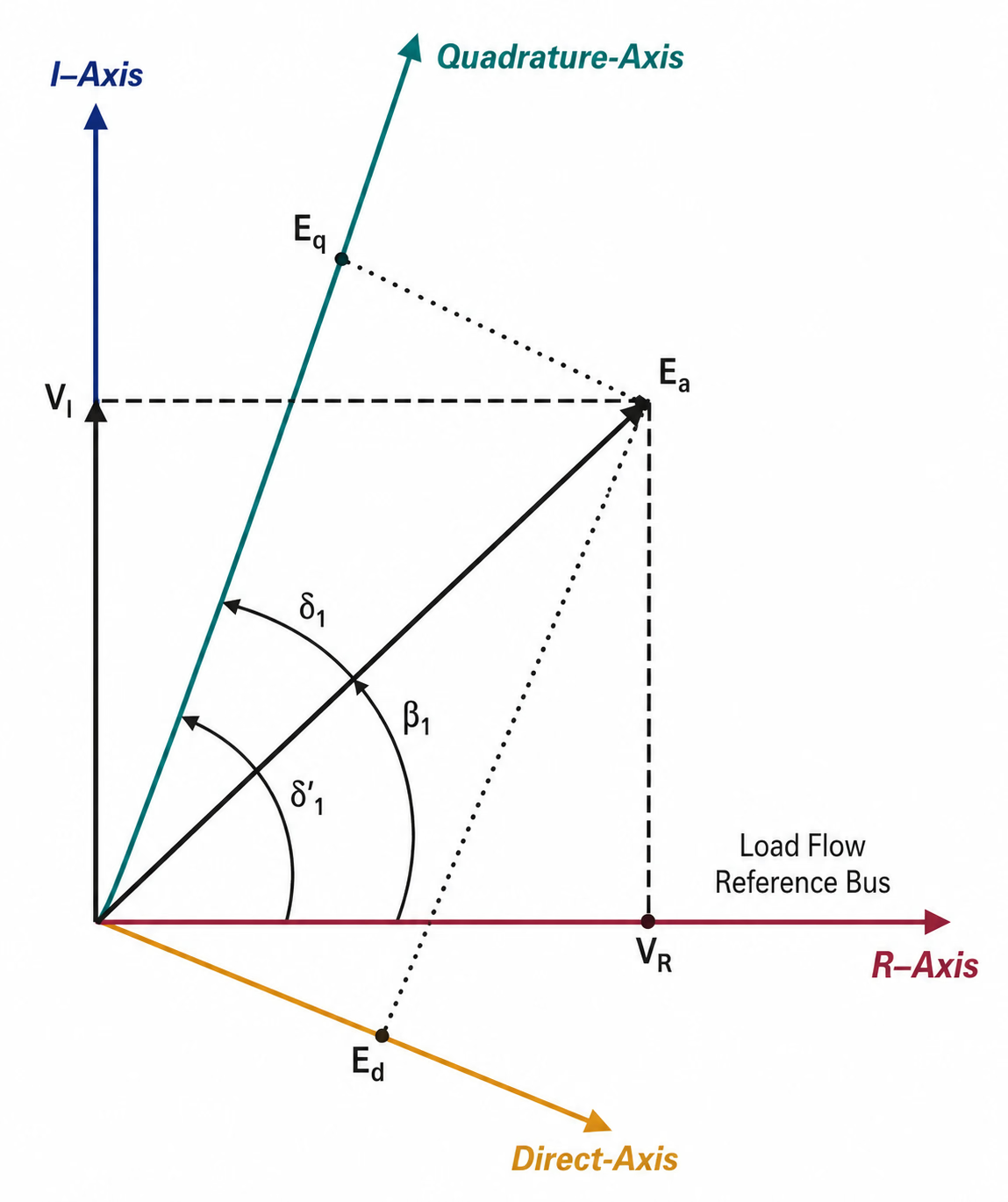
The dq0 variables are defined in a rotor-fixed reference frame, while the external network is normally expressed in a stationary or synchronously rotating network reference frame. Therefore, when EMTP® machine quantities are compared with terminal phasors, real/imaginary voltage components or another simulation tool, the angular relationship between the d/q axes and the network reference axes must be clear. This is also why the q-axis leading/lagging convention and the rotor-angle definition must be applied consistently.

IEEE Std 1110-2019 Figure 4: the rotor-fixed d and q axes shown against the network real (R) and imaginary (I) reference axes, with the angle between the two reference frames.
Figure 1 — Relationship between the rotor-fixed d/q axes and the external real/imaginary reference axes. The figure helps clarify how the machine internal reference frame is related to terminal/network quantities when interpreting EMTP® dq0 variables.

Note — Use this figure only as a reference-frame interpretation aid. It should not replace the Park transformation matrix, the q-axis convention statement, or the inverse transformation used to recover the physical phase quantities.

Section 7

dq0 flux-linkage equations

After transformation the flux-linkage equations simplify markedly: the stator d-axis winding couples only with d-axis rotor circuits, the q-axis winding only with q-axis rotor circuits, and the zero-sequence winding with neither. This is the key structural simplification:

\[ \begin{bmatrix}\boldsymbol{\psi}_{dq0} \\ \boldsymbol{\psi}_r\end{bmatrix} = \begin{bmatrix}\mathbf{L}'_{ss} & \mathbf{L}'_{sr} \\ \mathbf{L}'_{rs} & \mathbf{L}_{rr}\end{bmatrix}\begin{bmatrix}\boldsymbol{i}_{dq0} \\ \boldsymbol{i}_r\end{bmatrix} \qquad \mathbf{L}'_{ss} = \begin{bmatrix}L_d & 0 & 0 \\ 0 & L_q & 0 \\ 0 & 0 & L_0\end{bmatrix} \]
\(\boldsymbol{\psi}_{dq0},\ \boldsymbol{i}_{dq0}\)
stator flux-linkage and current vectors in dq0 form
\(\boldsymbol{\psi}_r,\ \boldsymbol{i}_r\)
rotor flux-linkage and current vectors (field and damper circuits)
\(\mathbf{L}'_{ss},\ \mathbf{L}'_{sr},\ \mathbf{L}'_{rs}\)
transformed stator-stator, stator-rotor and rotor-stator inductance matrices (prime = dq0 frame)
\(\mathbf{L}_{rr}\)
rotor-rotor inductance matrix
\(L_d,\ L_q,\ L_0\)
direct-, quadrature- and zero-sequence stator inductances

The transformed stator-stator matrix is diagonal in the ideal symmetrical case — one of the main benefits of Park’s transformation. It separates the stator magnetic behaviour into independent direct, quadrature and zero-sequence channels.

Section 8

Direct- and quadrature-axis coupling

In the dq0 frame the d-axis stator winding is aligned with the field and d-axis damper, so the d-axis flux linkage depends on the d-axis stator current, the field current and the d-axis damper current:

\[ \psi_d = L_d\,i_d + M_{dF}\,i_F + M_{dD}\,i_D \]
\(\psi_d,\ L_d,\ i_d\)
d-axis stator flux linkage, inductance and current
\(M_{dF},\ i_F\)
d-axis-to-field mutual inductance and field current
\(M_{dD},\ i_D\)
d-axis-to-d-damper mutual inductance and d-damper current

This shows the structure rather than every damper branch: d-axis stator flux is coupled to the d-axis rotor circuits.

\[ \psi_q = L_q\,i_q + M_{qQ1}\,i_{Q1} + M_{qQ2}\,i_{Q2} \qquad\qquad \psi_0 = L_0\,i_0 \]
\(\psi_q,\ L_q,\ i_q\)
q-axis stator flux linkage, inductance and current
\(M_{qQ1},\ M_{qQ2}\)
q-axis-to-q-damper mutual inductances
\(i_{Q1},\ i_{Q2}\)
q-axis damper currents
\(\psi_0,\ L_0,\ i_0\)
zero-sequence flux linkage, inductance and current (no rotor coupling)

There is no coupling between the q-axis stator winding and the d-axis field in the ideal model because the axes are orthogonal, and the zero-sequence circuit has no rotor coupling at all (its handling in ground-fault studies was described earlier).

Section 9

Reciprocal mutual inductances

A physically reciprocal magnetic system should have equal mutual inductances in both directions — the coupling from winding A to B equal to that from B to A, with consistent scaling. In the transformed dq0 system this reciprocity is not automatic for an arbitrary choice of transformation constants; the transformed stator-to-rotor and rotor-to-stator mutual inductances become equal only when the d- and q-axis scaling constants satisfy the power-invariant condition. This is a further reason the power-invariant Park transformation is attractive: it preserves both the power relationships and a reciprocal, symmetric mutual-inductance structure — useful in EMTP®-type modelling for numerical and energy consistency.

Section 10

dq0 voltage equations and speed voltage

The phase-domain voltage equations contain resistance drops and flux derivatives. When the reference frame rotates, the derivative of the flux linkage contains an additional coupling term, so after transformation the stator equations gain one extra physical effect — speed voltage. These terms are not extra physical windings; they are the mathematical result of observing the machine from a frame rotating with the rotor. The equations below use the generator convention (positive stator current flows out of the machine); the sign of the speed-voltage terms follows the selected q-axis convention:

\[ v_d = -R_a\,i_d - \frac{d\psi_d}{dt} - \omega\,\psi_q \] \[ v_q = -R_a\,i_q - \frac{d\psi_q}{dt} + \omega\,\psi_d \] \[ v_0 = -R_a\,i_0 - \frac{d\psi_0}{dt} \]
\(v_d,\ v_q,\ v_0\)
d-, q- and zero-sequence stator voltages
\(i_d,\ i_q,\ i_0\)
d-, q- and zero-sequence stator currents
\(\psi_d,\ \psi_q,\ \psi_0\)
d-, q- and zero-sequence flux linkages
\(R_a\)
stator (armature) resistance
\(\omega\;(\omega_e)\)
electrical angular speed of the rotating reference frame (rad/s)
\(d/dt\)
time derivative
\(\omega\,\psi_q,\ \omega\,\psi_d\)
speed-voltage cross-coupling terms (sign set by the d/q convention)

The speed-voltage terms arise because a flux linkage stationary in the rotor frame is seen as moving relative to the stator, inducing voltage. The d-axis voltage is influenced by the q-axis flux and vice-versa. At standstill \(\omega=0\) and the speed terms vanish; at synchronous speed they form the steady-state internal voltage; during a transient, changes in rotor speed and flux feed directly into them. These are not artificial terms — they are the fundamental electromechanical voltage of rotation.

Section 11

Rotor voltage equations

The transformation is applied to the stator quantities; the rotor quantities already live on the rotor axes, so the rotor equations need no transformation. The rotor windings use the passive (motor) convention — current flows into each winding — complementing the generator convention used for the stator, so their signs are positive. The field winding has an applied voltage, while the short-circuited dampers have zero terminal voltage:

\[ v_F = R_F\,i_F + \frac{d\psi_F}{dt} \] \[ 0 = R_D\,i_D + \frac{d\psi_D}{dt} \qquad 0 = R_{Q1}\,i_{Q1} + \frac{d\psi_{Q1}}{dt} \qquad 0 = R_{Q2}\,i_{Q2} + \frac{d\psi_{Q2}}{dt} \]
\(v_F,\ R_F,\ i_F,\ \psi_F\)
field voltage, resistance, current and flux linkage
\(R_D,\ R_{Q1},\ R_{Q2}\)
damper-winding resistances (d-axis and two q-axis)
\(i_D,\ i_{Q1},\ i_{Q2}\)
damper currents
\(\psi_D,\ \psi_{Q1},\ \psi_{Q2}\)
damper flux linkages

The zero right-hand side on the damper equations is exactly why damper currents arise on their own during a disturbance: they are not imposed externally but induced by the changing flux linkages.

Section 12

Electromagnetic torque in dq0 form

In the phase domain the torque comes from the derivative of magnetic coenergy with rotor position. In the power-invariant dq0 frame it collapses to the familiar compact form:

\[ T_e = \frac{N_p}{2}\left(\psi_d\,i_q - \psi_q\,i_d\right) \]
\(T_e\)
electromagnetic torque
\(N_p\)
number of poles (\(N_p/2\) = pole pairs)
\(\psi_d,\ \psi_q\)
d- and q-axis stator flux linkages
\(i_d,\ i_q\)
d- and q-axis stator currents

Torque is the interaction between d-axis flux and q-axis current, and between q-axis flux and d-axis current. For a non-salient machine it is largely the rotor field flux acting with \(i_q\); for salient-pole machines the \(L_d\neq L_q\) difference adds a reluctance-torque component. The same expression explains severe transient torque: large oscillations in \(i_d,i_q,\psi_d,\psi_q\) during faults or switching produce large torque oscillations — the reason machine modelling matters for shaft-duty and torsional studies. The factor \(N_p/2\) appears because the dq equations use electrical radians while mechanical torque relates to mechanical angle; for an \(N_p\)-pole machine the pole pairs are \(N_p/2\), and this must be handled correctly when moving between electrical and mechanical speed, angle and torque.

Section 13

Reading transients through dq0 variables

The dq0 variables are also powerful diagnostics, not just numerical conveniences. The d-axis current shows whether the stator current is magnetising or demagnetising the field axis; the q-axis current tracks torque production; the field current shows the excitation and rotor-flux response; the damper currents reveal the subtransient rotor response; the d- and q-axis flux linkages show the magnetic state of each axis; the electromagnetic torque shows the mechanical stress imposed by the electrical system; and the rotor speed and angle show the mechanical response.

  • During a terminal fault, the dq variables reveal how the initial subtransient current is supported by damper circuits and flux continuity.
  • During load rejection, they show how flux, torque and speed move after the electrical power changes suddenly.
  • During out-of-phase switching, they show why the torque can become severe.
  • During subsynchronous resonance, they show the interaction between electrical torque and shaft modes.

For this reason a good EMTP® machine study should not plot only phase voltages and currents — it should observe the relevant dq variables and torque signals.

Section 14

Balanced operation and zero-sequence neglect

Under balanced three-phase operation the phase quantities sum to zero, so the zero-sequence component is zero and the dq0 model reduces to a dq model — which is why many machine analyses use only the d and q axes. As covered earlier, this simplification must not be applied to unbalanced or ground-fault conditions, where zero-sequence behaviour can matter.

The rule

Ignore zero sequence only when the physical condition is balanced, or when the zero-sequence path is demonstrably irrelevant.

Section 15

Connection with EMTP® modelling

In EMTP® the Park transformation is part of the internal synchronous-machine solution — the user does not build the transformation matrix by hand — but understanding it is essential for interpreting results and entering data correctly. The dq0 framework is how the program represents stator electrical behaviour, field- and damper-winding dynamics, the flux-current relationships, speed-voltage coupling, electromagnetic torque, rotor mechanical interaction and saturation where included.

This is also why EMTP® asks for d- and q-axis reactances and time constants, field data and damper representation: those parameters correspond to the physical axes of the transformed machine. A user thinking only in phase quantities may not see why the d-axis synchronous, transient and subtransient reactances \(X_d, X'_d, X''_d\), their q-axis counterparts and the d-axis short-circuit time constants \(T'_d, T''_d\) are needed — the dq0 model explains their role. The full subtransient, transient and steady-state behaviour behind these symbols is covered on the parameters and short-circuit response page; here they appear only as a bridge to it.

After transformation and initialisation, a few quick checks confirm the dq0 model is behaving:

  • The reconstructed abc voltages and currents are physically sensible.
  • Active and reactive power agree between the abc and dq0 frames.
  • The zero-sequence current is zero when no zero-sequence path exists.
  • The torque sign is consistent with generator or motor operation.
  • The steady-state dq quantities are stable before the disturbance is applied.

Section 16

Common modelling mistakes

Avoid these
  • Mixing Park-transformation scaling conventions between software, textbook and manufacturer data.
  • Mixing q-axis leading and q-axis lagging sign conventions.
  • Using dq quantities without checking whether they are peak, RMS or power-invariant values.
  • Confusing the zero-sequence component with a rotor-coupled axis.
  • Using the same symbol for instantaneous power and pole count.
  • Comparing EMTP® dq outputs with another tool without checking the axis convention.
  • Applying torque or power formulas from a different convention.
  • Using reactance symbols before confirming their base and saturation basis.
  • Trusting a dq result without checking the reconstructed abc terminal quantities.

Section 17

Where this fits in the series

This guide follows Synchronous Machine Representation for EMT Studies, which sets out the phase-domain machine and why its representation depends on the transient frequency range. The dq0 equations derived here are the basis for the per-unit d-axis and q-axis equivalent circuits used on the next page, Per-Unit Representation and Equivalent Circuits. The later pages then explain how reactances and time constants (parameters and short-circuit response), magnetic saturation and data conversion are turned into the parameters that populate those circuits.

Section 18

Suggested report wording

Model statement — for a study report

“The synchronous-machine stator quantities were transformed into the rotating dq0 reference frame using a consistent Park transformation convention. The d-axis was aligned with the rotor field axis, the q-axis convention was maintained consistently for voltage, current, flux linkage, torque and power, and the zero-sequence component was included where a zero-sequence path was represented. The resulting dq0 equations formed the basis for the EMTP® machine model and the subsequent per-unit equivalent-circuit parameterisation.”

Section 19

Main takeaway

Park’s transformation is the bridge between the real machine and the EMTP® model

Park transformation is not just a mathematical change of variables — it is the step that turns rotor-position-dependent phase-domain equations into a practical rotating-frame model. Once the d-axis, q-axis, zero-sequence component, scaling convention and sign convention are defined consistently, the dq0 equations provide the foundation for EMTP® synchronous-machine equivalent circuits, torque calculation and transient-response studies.

References

References

The reference text for the derivation, R. H. Park’s original two-reaction theory, and the standard machine-modelling works behind this page.

  1. J. A. Martínez-Velasco, Ed., Power System Transients: Parameter Determination, Ch. 5 (Synchronous Machines). Boca Raton, FL, USA: CRC Press, 2010.
  2. R. H. Park, “Two-reaction theory of synchronous machines — generalized method of analysis, Part I,” Transactions of the AIEE, vol. 48, no. 3, pp. 716–727, Jul. 1929.
  3. P. Kundur, Power System Stability and Control. New York, NY, USA: McGraw-Hill, 1994.
  4. P. C. Krause, O. Wasynczuk and S. D. Sudhoff, Analysis of Electric Machinery and Drive Systems. Piscataway, NJ, USA: IEEE Press / Wiley.
  5. IEEE Std 1110-2019 (Revision of IEEE Std 1110-2002), IEEE Guide for Synchronous Generator Modeling Practices and Parameter Verification with Applications in Power System Stability Analyses. Piscataway, NJ, USA: IEEE, 2020.
  6. CIGRE Working Group 33.02, Guidelines for Representation of Network Elements when Calculating Transients, Technical Brochure 39. Paris, France: CIGRE, 1990.

Nine-Part Technical Series

Synchronous Machine Modelling in EMTP®

A nine-part guide to representing the synchronous machine in EMTP® — from the modelling overview and EMT representation, through the dq0 transformation, per-unit equivalent circuits, parameters, data conversion and tests, to magnetic saturation and high-frequency/shaft modelling.

Part Three Reading now

Park Transformation and dq0

How Park’s transformation maps the time-varying phase-domain equations into the rotating dq0 frame: direct, quadrature and zero-sequence components, speed voltage and torque.

Series progress 3 of 9