Overview & Model-Selection Guide

Synchronous Machine Modelling in EMTP®

In EMTP® (the Electromagnetic Transients Program) a synchronous machine is represented as a coupled electrical, magnetic and mechanical system rather than a fixed source behind a reactance. The model includes the stator and rotor windings, their magnetic coupling, saturation, damper-winding effects, mechanical inertia and, where required, shaft dynamics — so the simulation can reproduce fault-current decay, torque oscillations, load rejection, synchronisation, unbalanced faults and other electromagnetic-transient behaviour. This page is the overview and decision guide: it explains what the model contains and how to choose the level of detail, and links to the specialist pages for each derivation.

Reading time ≈ 22 min · Start here, then go to the specialist pages

This guide introduces each part of the EMTP® synchronous-machine model and points to the page that develops it in full. Treat it as the map of the synchronous-machine series — read it first, then follow the links for the derivations, parameter conversion and specialist studies.
Abbreviations used on this page
EMTP®Electromagnetic Transients Program
SMSynchronous machine (wound-field)
PMSMPermanent-magnet synchronous machine
dq0Direct / quadrature / zero-sequence axes
AVRAutomatic voltage regulator (excitation control)
SSRSubsynchronous resonance
\(\omega_e,\ \omega_m\)Electrical and mechanical angular speed (rad/s)
\(T_e,\ T_m\)Electromagnetic and mechanical torque
Key idea
  1. The machine is a coupled electrical–magnetic–mechanical system — stator network, rotor flux, damper currents, saturation, torque and shaft motion all shape the transient.
  2. EMTP® works in the dq0 (Park) frame so the stator–rotor couplings become constant and the equations solve efficiently.
  3. The right model is the one that includes the effects controlling the study — not the most complex one — initialised from a consistent operating point.
  4. This page is the overview; the specialist pages carry the derivations, parameter conversion, saturation curves, short-circuit response and high-frequency / shaft detail.
Key terms used on this page
01Direct / quadrature axis
Rotor reference axes; the d-axis aligns with the field, the q-axis is 90 electrical degrees ahead.
02Zero-sequence
The common-mode stator component; matters mainly for unbalanced and ground-fault studies.
03Field winding
The excited d-axis rotor winding producing the main flux in a wound-field machine.
04Damper winding
Short-circuited rotor circuits that govern the subtransient (first-cycle) response and damping.
05Synchronous / transient / subtransient reactance
\(X_d\), \(X'_d\), \(X''_d\) (and \(X_q\)): effective reactances at successive time scales.
06Saturation
The nonlinear fall in the mutual air-gap inductance as iron flux rises.
07Canay reactance
An extra d-axis leakage term improving the field–damper match during parameter conversion.
08Per-unit base
The reference power, voltage, current and impedance used to normalise the machine data.
09Inertia constant \(H\)
The kinetic energy stored at rated speed divided by the rated apparent power, in seconds.
10Multi-mass shaft
Turbine, generator and exciter rotors as separate inertias joined by elastic shafts.

Section 1

Why a detailed machine model is needed

In steady state a generator can look like a voltage behind a reactance, but during a disturbance the internal flux linkages cannot change instantly: currents are induced in the field and damper windings, the electromagnetic torque \(T_e\) changes, the rotor accelerates or decelerates, the shaft may oscillate, and saturation may alter the magnetic coupling. The terminal voltage and current are the result of this coupled electromagnetic and mechanical process. That is why EMTP® solves the machine’s electrical and mechanical equations in the time domain rather than treating it as a static source — and why the level of detail must match the study, from a reduced representation for a simple fault-current envelope to a full model for load rejection, subsynchronous resonance or shaft-torque work.

Section 2

Machine types in EMTP®

EMTP® provides two synchronous-machine devices. The conventional wound-field synchronous machine (SM) has a three-phase stator, a d-axis field winding supplied by an excitation system, and damper windings on the d- and q-axes. The permanent-magnet synchronous machine (PMSM) has permanent magnets on the rotor producing a constant d-axis flux, with optional dampers. The essential difference is the source of the rotor flux — field current versus permanent magnets — and both are solved in the same dq0 framework. The PMSM is covered on its own below.

Section 3

The device and its interface

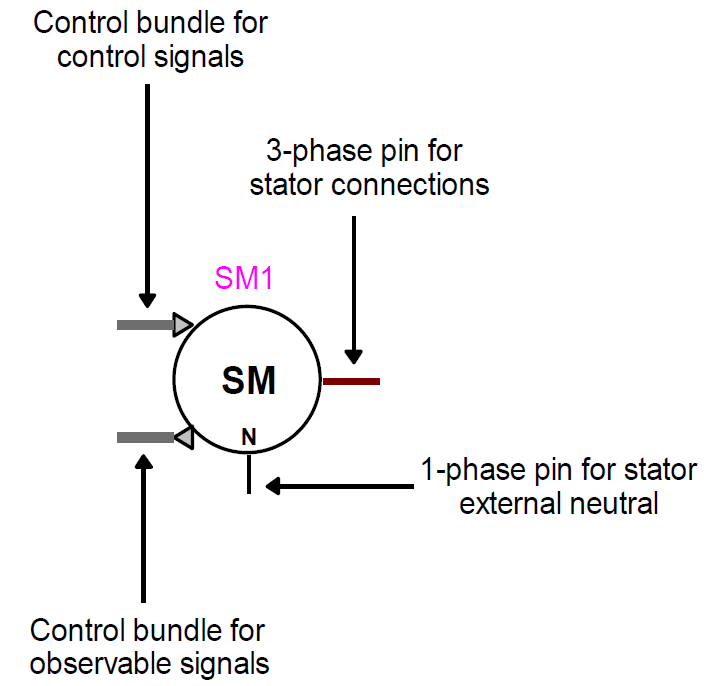
In the schematic the machine is a three-phase electrical component with extra control and observation interfaces. The three-phase stator terminal exchanges power with the network; the neutral terminal sets the stator neutral connection (important for ground-fault and unbalanced studies); the control bundle accepts external inputs such as mechanical power or torque, excitation or governor signals; and the observe bundle exposes internal variables — rotor speed and angle, electromagnetic and shaft torque, field current, damper quantities, stator currents and dq variables. A good model is both electrically correct and dynamically observable.

The EMTP synchronous-machine device symbol with the three-phase stator terminal, neutral terminal, control bundle and observable-signal bundle.
Figure 1 — The EMTP® synchronous-machine device as the user sees it — the three-phase stator terminal, the neutral terminal, the control bundle (inputs such as mechanical torque or field voltage) and the observable-signal bundle (outputs such as speed, angle and torque).

Section 4

Physical structure

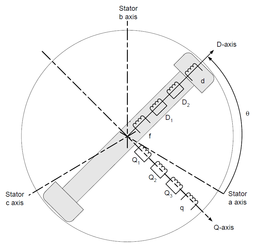
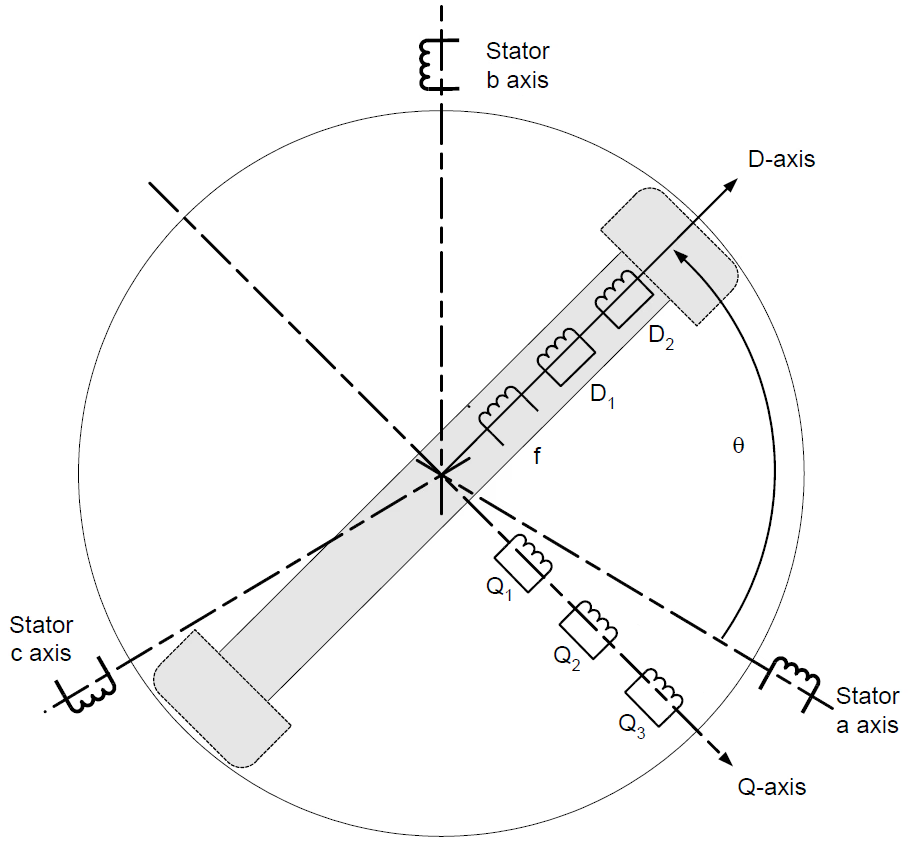
The wound-field machine has three parts: the three-phase stator (armature windings a, b, c, displaced by 120 electrical degrees); the rotor field winding on the direct axis, which produces the main flux; and the damper windings — short-circuited rotor circuits representing fast transient effects. In EMTP® the machine can carry up to nine coupled windings: three stator windings, one field winding, up to two further d-axis dampers and up to three q-axis dampers — enough to reproduce subtransient and transient response and damping for most practical machines.

Schematic of the synchronous machine in the rotor reference frame, showing stator phase axes, the field winding on the d-axis and damper windings on the d- and q-axes.
Figure 2 — The machine in the rotor reference frame: the stator phase axes, the field winding on the direct (d) axis, and the damper windings on the d- and quadrature (q) axes.

Section 5

The dq0 (Park) idea

The stator windings are stationary while the rotor turns, so in phase coordinates the stator–rotor inductances vary continuously with rotor position. Park’s transformation projects the three stator phase quantities onto axes that rotate with the rotor: a direct-axis (d) component aligned with the rotor field, a quadrature-axis (q) component 90 electrical degrees ahead of the d-axis, and a zero-sequence (0) component — the common part of the three phases, which matters mainly for unbalanced or ground-fault studies. In this frame the main magnetic couplings become constant, so the equations are far easier to solve in EMTP®. The full derivation, the flux-linkage and voltage equations and the speed-voltage coupling are on the Park transformation and dq0 representation page.

\[ \omega_e = \frac{d\theta}{dt} \qquad\qquad \omega_m = \frac{2}{p}\,\omega_e \]
\(\omega_e\)
electrical angular speed (rad/s) — the speed of the dq frame
\(\theta\)
electrical rotor angle
\(\omega_m\)
mechanical angular speed (rad/s)
\(p\)
number of poles; the number of pole pairs is \(p/2\)

Electrical and mechanical speed (and angle) are equal only for a two-pole machine; for any other pole count the factor \(2/p\) must be applied.

Schematic of the machine after Park's transformation, the stator represented by d-axis, q-axis and zero-sequence windings rotating with the rotor.
Figure 3 — After Park’s transformation the three stator phase windings become equivalent d-axis, q-axis and zero-sequence windings that rotate with the rotor, so the main magnetic couplings become constant.

Section 6

Damper windings and the first cycles

Damper windings are short-circuited rotor circuits, essential for the fast response just after a disturbance. When the stator flux changes suddenly the dampers carry induced currents that oppose the change, so they shape the subtransient (first-cycle) current, the damping of oscillations and the electromagnetic torque. The d-axis dampers govern the d-axis subtransient behaviour; the q-axis dampers govern the q-axis behaviour and matter especially for round-rotor machines (where the solid rotor provides extra current paths) and for torsional studies. Too few dampers can give an unrealistic initial current or torque. How the dampers set the subtransient reactance and time constants, and the full short-circuit response, are on the machine parameters and short-circuit response page.

Section 7

Magnetic saturation

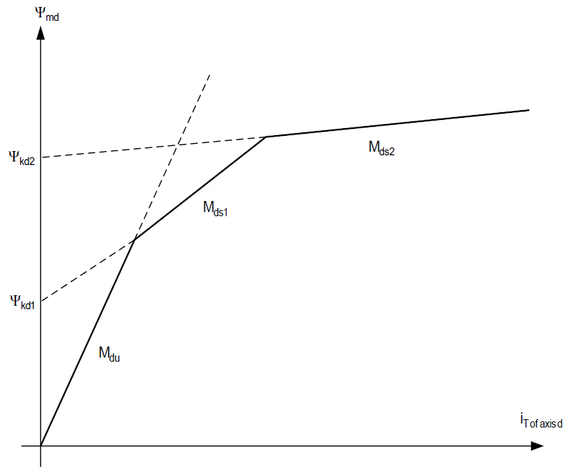
Saturation is applied to the mutual air-gap path, not to the leakage inductances: the leakage flux is treated as non-saturable, while the mutual (magnetising) flux falls below the linear value as the iron saturates. It matters most for load rejection, terminal overvoltage, transformer energisation near a generator, severe faults, abnormal excitation and voltage recovery — whenever the machine operates well away from the linear region. Saturated and unsaturated parameters must not be mixed without checking, or the model will not reproduce the intended voltage and field-current relationship. The open-circuit characteristic behind the curve, the short-circuit ratio and the saturation factor are developed on the magnetic saturation page.

Piecewise-linear d-axis saturation model relating the mutual air-gap flux to the magnetising current.
Figure 4 — Piecewise-linear saturation of the mutual air-gap flux: only the mutual (magnetising) path saturates, while the leakage flux is treated as linear.

Section 8

Parameters: from data sheet to model

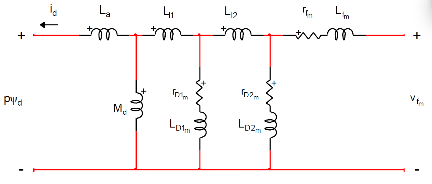
A manufacturer normally gives characteristic data — the d-axis synchronous, transient and subtransient reactances \(X_d\), \(X'_d\), \(X''_d\) (and their q-axis counterparts \(X_q\), \(X''_q\)), the open- and short-circuit time constants, armature resistance and the saturation curve. EMTP® needs the internal equivalent-circuit parameters (stator, field and damper resistances and inductances), so a conversion or parameter-fitting step is required — a reactance such as \(X''_d\) is not a physical inductor but the effect of several windings together. The Canay reactance may be used to improve the d-axis field–damper match. The converted model must always be checked against the expected short-circuit current and against stable no-disturbance operation. The conversion procedures and Canay’s inductance are on the data-conversion page; the tests that produce the data are on the test-procedures page.

d-axis equivalent circuit solved in EMTP, showing the field winding, d-axis damper and the Canay leakage path.
Figure 5 — The d-axis equivalent circuit EMTP® solves, with the field winding, the d-axis damper, and the Canay leakage path that links the field and damper but not the stator winding.

Section 9

Per-unit bases

Machine data is usually in per unit, which EMTP® converts to SI. The engineering essentials for this overview: the base apparent power (MVA), voltage, current and impedance must be consistent; the rotor quantities must be referred to the selected stator / base convention; and a wrong base — the wrong MVA, or a phase voltage used where a line-to-line value belongs — can produce a model that converges numerically yet gives physically wrong currents, fluxes or torque. The inertia constant \(H\) (the kinetic energy stored at rated speed divided by the rated apparent power, in seconds) is one convenient base-related figure to check. The full base set and the equal-air-gap-flux rotor referral are on the per-unit and equivalent-circuits page.

Section 10

Initialisation

An EMT machine simulation should not start from zero states: the internal flux linkages, rotor angle, field current, stator current and torque must match the pre-disturbance operating point. EMTP® performs a steady-state initialisation, and the machine can be linked to a load-flow solution so its terminal voltage and angle come straight from the network case — important when several machines share a bus and the power must be split correctly. A short no-disturbance run should then confirm the model is stable before any event is applied; a model that drifts before the disturbance is not correctly initialised.

Section 11

Time-domain solution

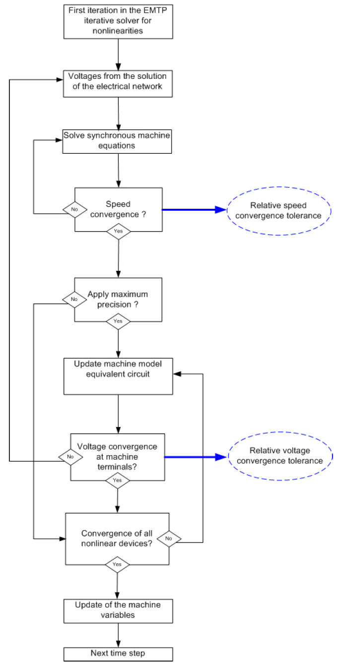
In the time domain the machine is a nonlinear component solved together with the network at each step: the network sets the stator voltages and currents, the machine sets the internal fluxes, rotor currents, torque and speed, and the mechanical equations set the rotor motion — all coupled in a loop. EMTP® uses an internal rotor-speed loop for each machine, and at maximum precision the machine joins the nonlinear iterative solution with the rest of the network until convergence. Higher precision improves accuracy but costs run time, so precision settings should be changed with care and checked by sensitivity rather than adjusted blindly.

Flowchart of the EMTP synchronous-machine iterative solution with the internal speed loop and optional voltage-convergence loop.
Figure 6 — How EMTP® solves the machine at each time step: an internal rotor-speed loop and, at higher precision, an outer voltage-convergence loop shared with the rest of the network.

Section 12

Mechanical model and shaft

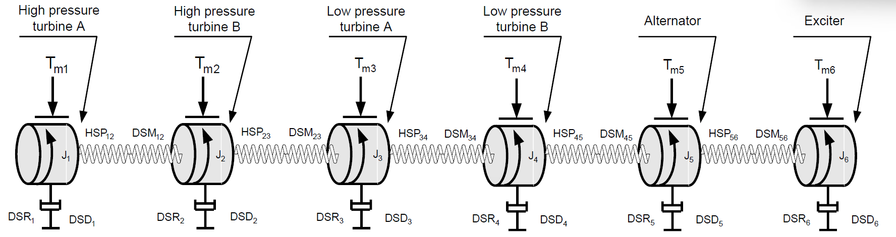
The electromagnetic model is coupled to a mechanical one through the torque. A single equivalent inertia is enough when only the overall rotor motion matters; a multi-mass shaft — turbine sections, generator rotor and exciter as separate inertias joined by elastic shafts with stiffness and damping — is needed when shaft torsion matters (subsynchronous resonance, series compensation, shaft-torque or out-of-phase-switching duty). For a single mass the rotor obeys a simple swing equation, with the electromagnetic torque computed from the dq fluxes and currents:

\[ J\,\frac{d\omega_m}{dt} = T_m - T_e \qquad\qquad T_e = \frac{p}{2}\left(\psi_d\,i_q - \psi_q\,i_d\right) \]
\(J\)
moment of inertia of the rotating mass
\(\omega_m\)
mechanical angular speed
\(T_m,\ T_e\)
mechanical (prime-mover) and electromagnetic torque
\(p\)
number of poles
\(\psi_d,\ \psi_q\)
d- and q-axis flux linkages
\(i_d,\ i_q\)
d- and q-axis stator currents

For a multi-mass shaft this becomes a matrix equation in which each shaft section has a stiffness \(K\) (the twist torque per unit angle difference) and a damping \(D\). The multi-mass shaft, torsional modes and the high-frequency winding model for steep-front surges are on the high-frequency and shaft modelling page.

Multi-mass turbine-generator shaft model with rotor masses connected by massless springs and damping elements.
Figure 7 — A multi-mass turbine-generator shaft — turbine sections, generator rotor and exciter as separate inertias joined by elastic shafts — used when shaft torsion matters.

Section 13

The permanent-magnet machine (PMSM)

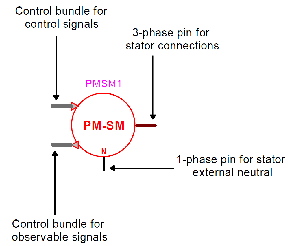
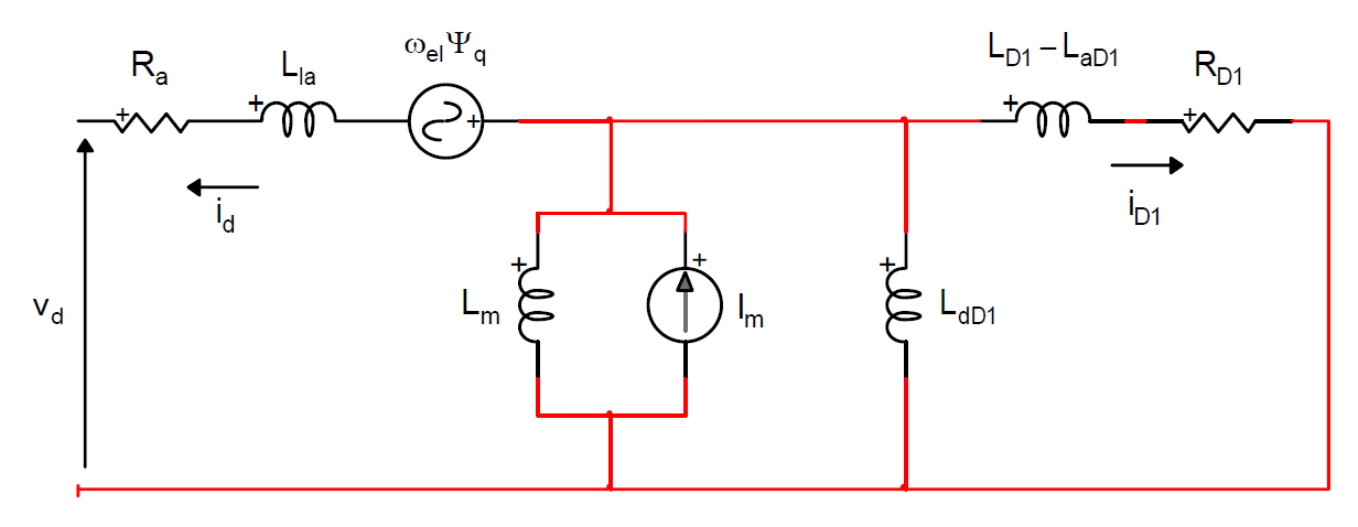
The PMSM shares the three-phase stator and the dq0 framework, but its rotor flux comes from permanent magnets rather than a field winding, so it has no field-voltage control in the sense a wound-field machine does. In EMTP® the magnet is represented as a constant d-axis flux (by an equivalent magnet flux, an equivalent magnet current, or a magnet inductance and current), optionally with dampers. In practical grid studies a PMSM is almost always converter-fed, and the converter and its controls usually dominate the observed response — current limits and converter blocking can matter more than the bare machine equations. A PMSM study must therefore state clearly what the model represents: the machine alone, the machine with ideal torque/speed control, an average-value converter, a detailed converter, or the full grid-side converter system. Without that boundary the term “PMSM model” is ambiguous.

The EMTP permanent-magnet synchronous-machine device symbol.
Figure 8 — The EMTP® permanent-magnet synchronous-machine (PMSM) device symbol, with the same stator, neutral, control and observe interface as the wound-field machine.
d-axis equivalent circuit of a permanent-magnet synchronous machine, the magnet shown as a constant flux source.
Figure 9 — The d-axis equivalent circuit of a PMSM: the permanent magnet appears as a constant flux source (an inductance in parallel with a constant current source) in place of a controllable field winding.

Section 14

Stator connection

The stator connection sets the zero-sequence and ground-fault behaviour. A wye stator with an accessible neutral can be grounded through an impedance (important for stator ground-fault and neutral-overvoltage studies); a delta stator blocks zero-sequence current from flowing into the network the way a grounded wye allows. For balanced positive-sequence work the connection may seem unimportant, but for ground faults, unbalanced faults, neutral overvoltage and protection studies it is critical, and it must match the real machine and transformer arrangement.

Section 15

Choosing the level of detail

The model should be selected for the transient being studied. The table summarises where to spend modelling effort.

Table 1 — Which machine features dominate, by study type. Use it to decide the required level of detail.
StudyWhat Controls the ResultShaft Model
Balanced 3-phase terminal faultd-axis subtransient / transient reactances; damper representationSingle mass
Unbalanced faultNegative- and zero-sequence response; stator connection & neutral groundingSingle mass
Load rejectionExcitation response and saturation (voltage rise); rotor accelerationSingle mass
Out-of-phase switchingSevere electromagnetic-torque stepMulti-mass
Subsynchronous resonanceShaft torsional modes; series compensation / converter controlsMulti-mass (essential)
Harmonic / frequency scanHarmonic impedance matrix (small-signal)Not applicable
Converter interaction (PMSM)Converter controls and current limitsPer drive

Model detail depends on the stability phenomenon

Model detail should follow the stability mechanism being studied, not the habit of reaching for the most detailed block or whichever one feels familiar. In large-disturbance rotor-angle studies the controlling behaviour may be the rotor-angle swing, the field-circuit response, excitation forcing, damper action and saturation at high flux levels — particularly with high-initial-response excitation or operation at the excitation ceiling. In small-disturbance studies the damping contribution of the field and damper circuits, the excitation controls and any power system stabiliser (PSS) can decide whether oscillations decay or grow. In voltage-stability studies the generator’s reactive-power capability, its field-current limits and the over- and under-excitation limiters of the automatic voltage regulator (AVR) often matter more than detailed subtransient behaviour. In frequency-stability studies the turbine/governor response, the protection and limiter behaviour, and the effect of speed deviation on induced voltage should be represented where they affect the conclusion — using torque-based acceleration rather than a power approximation when the frequency excursion is large.

Table 2 — Required machine-model detail by study objective.
Study ObjectiveRequired Model Focus
Large-disturbance angle stabilityRotor-angle swing, field circuit, excitation forcing, damper action and saturation at high flux.
Small-disturbance angle stabilityDamping torque from field and damper circuits, excitation controls and the stabiliser (PSS).
Voltage stabilityReactive capability, field-current limits, over- and under-excitation limiters, AVR support.
Frequency stabilityTurbine/governor, protection and V/Hz limiter, and the speed effect on voltage (torque-based).

Section 16

Build and verify the model

A clean overview workflow:

  1. Confirm the study objective and the outputs required (current, voltage, torque, speed, shaft torque…).
  2. Select the machine type and the stator connection.
  3. Confirm the rated data and base quantities (MVA, voltage, frequency, poles).
  4. Choose the model complexity from the available data — do not add detail the data cannot support.
  5. Apply saturation if the study can drive the machine into the nonlinear region.
  6. Initialise from the load-flow or steady-state operating point.
  7. Run a no-disturbance check and confirm the model stays steady.
  8. Apply the disturbance and validate the current, voltage, torque and speed response against expected behaviour.

The workflow says what to do; the next section says what to avoid.

Section 17

Common modelling mistakes

Avoid these
  • Mixing saturated and unsaturated parameters.
  • Mixing open-circuit and short-circuit time constants without conversion.
  • Using inconsistent MVA or voltage bases.
  • Treating manufacturer reactances as if they were the final internal inductances.
  • Using a single-mass shaft model when torsional interaction is part of the study.
  • Accepting a stable simulation without checking the result is physically consistent.

Section 18

Suggested report wording

Model statement — for a study report

“The synchronous machine was represented in EMTP® by a coupled dq0 electromechanical model — stator, field and damper circuits, magnetic saturation where relevant, and a single- or multi-mass shaft to suit the study. Parameters were converted from the manufacturer/test data to equivalent-circuit values on a consistent per-unit base, and the model was initialised from the load-flow operating point. A no-disturbance run confirmed stable initialisation before the event, and the fault-current, voltage, torque and speed responses were checked against expected behaviour.”

Section 19

Main takeaway

Select the model for the study

The engineer must select the synchronous-machine model according to the study objective, the available data and the required outputs. A reliable EMTP® model is not only a set of reactances — it is a consistent electromechanical representation with correct bases, the right saturation treatment, adequate damper representation, proper initialisation and validation. Start from this overview, then use the specialist pages for the dq0 derivation, the per-unit equivalent circuits, saturation, parameter conversion, the short-circuit response, and the high-frequency and shaft models.

References

References

The EMTP® device documentation and the foundational machine-modelling and standard references behind this overview.

  1. S. Dennetière, J. Mahseredjian and U. Karaagac, Synchronous Machine (SM) device documentation, EMTP-EMTPWorks.
  2. Permanent Magnet Synchronous Machine (PM-SM) device documentation, EMTP-EMTPWorks.
  3. H. W. Dommel, EMTP Theory Book. Vancouver, BC, Canada: Microtran Power System Analysis Corporation, 1996.
  4. U. Karaagac, J. Mahseredjian and O. Saad, “An efficient synchronous machine model for electromagnetic transients,” IEEE Transactions on Power Delivery, vol. 26, no. 4, pp. 2456–2465, Oct. 2011.
  5. IEEE Std 115-2009, IEEE Guide for Test Procedures for Synchronous Machines. New York, NY, USA: IEEE.
  6. IEEE Std 1110-2002, IEEE Guide for Synchronous Generator Modeling Practices and Applications in Power System Stability Analyses. New York, NY, USA: IEEE.
  7. IEC Publication 34-4A, Recommendations for Rotating Electrical Machinery. Geneva, Switzerland: International Electrotechnical Commission, 1972.

Nine-Part Technical Series

Synchronous Machine Modelling in EMTP®

A nine-part guide to representing the synchronous machine in EMTP® — from the modelling overview and EMT representation, through the dq0 transformation, per-unit equivalent circuits, parameters, data conversion and tests, to magnetic saturation and high-frequency/shaft modelling.

Part One Reading now

Synchronous Machine Modelling: Overview

Why the synchronous machine has no single universal model, and how the required level of detail follows from the study objective and the transient frequency range in EMTP®.

Series progress 1 of 9