Renewable Modelling · Inverter Characteristics

Inverter Characteristics for IBG Modelling

An inverter-based generator is really two things: a primary energy source, and the inverter that couples it to the grid. For dynamic studies it is the inverter that matters — its topology, its control, its protection and its ancillary functions decide how the plant behaves. This guide opens up that inverter: the PV converter chain from array to grid, how the control makes the ac current follow the point-of-common-coupling voltage, when an average model is enough and when you need a switching model, the grid-code functions of EU 2016/631 and IEEE 1547, the split between internal and interface protection, and how it all reduces to three modelling classes — Control, Protection and Capability — for an EMTP® study. It is the companion to our guide on the characteristics of inverter-based generation.

Reading time ≈ 26 min · Topology, control, protection & primary sources

The opening guide explained why inverter-based generation behaves differently from synchronous machines — the services that are physics for a machine are control for an inverter. This page opens the inverter itself: its topology, the dc/ac chain, control, protection and the capability functions grid codes require.

IBG stands for inverter-based generation — and, loosely, an inverter-based generator: any source that reaches the grid through a power-electronic inverter rather than a directly-connected rotating machine. Solar photovoltaic (PV) plants, most modern wind turbines and battery storage are all IBG. Behind each of them sits some primary energy source, but for a power-system dynamic study the part that decides how the plant behaves is the inverter — the grid-facing converter and its control software. This page opens up that inverter, from the hardware outward.

How to read this page

This is the second guide in a nine-part series on modelling inverter-based generation, and it is the foundation for the rest. Here we build up the inverter itself — its hardware (topology and the PV converter chain), its control, its protection, and the capability functions a grid code can demand. The later parts take these same building blocks and ask which of them a particular study actually needs: for frequency stability, voltage stability, RMS modelling, EMT modelling and control-interaction studies. Read this page as the vocabulary; the later pages are the grammar.

Abbreviations used on this page
IBGInverter-based generation (or generator)
PVPhotovoltaic
PCCPoint of common coupling (plant–grid connection point)
PLLPhase-locked loop (grid angle / frequency tracker)
MPPTMaximum power point tracking
PWMPulse-width modulation
NPCNeutral-point-clamped inverter
LCLInductor–capacitor–inductor output filter
DC-ACRDC automatic current regulator
DC-AVRDC automatic voltage regulator
FRTFault ride-through
LVRTLow-voltage ride-through
HVRTHigh-voltage ride-through
ROCOFRate of change of frequency
PODPower oscillation damping
DFIGDoubly-fed induction generator
WTGWind-turbine generator
ORCOrganic Rankine cycle
RESRenewable energy source
EMIElectromagnetic interference
EMTElectromagnetic transient (time domain)
RMSRoot-mean-square (phasor) simulation
EMTP®Electromagnetic Transients Program
Key idea
  1. The inverter is an interface: using a PLL it converts the source’s dc into an ac current locked to the PCC voltage. At unity power factor that current is in phase with the voltage (pure active power); when reactive support is needed the control deliberately shifts its phase. One basic topology serves PV, wind, batteries and more.
  2. For most dynamic phenomena an average model — variables averaged over each switching period — reproduces the relevant low-frequency behaviour accurately; a detailed switching model is needed only when the switching itself is the point (harmonics, ripple, EMI, losses, device stress, filter resonance).
  3. Because the control is flexible software, grid codes (EU 2016/631, IEEE 1547) can require ancillary functions — P(f), Q(V), synthetic inertia, ROCOF immunity, ride-through, POD — but each is optional unless mandated, and you model only the ones a study depends on.
  4. For modelling, the inverter reduces to three classes — Control, Protection and Capability — and the primary source can often be neglected for short-term dynamics, though it still constrains the response the plant can achieve.
Key terms used on this page
01Inverter
The dc–ac converter that connects the plant to the ac grid; on this page “inverter” always means the grid-facing converter, not the PV-side stage.
02Chopper (dc–dc)
The boost dc–dc stage on the PV side that raises the array voltage and carries out MPPT; kept distinct from the inverter throughout.
03Average model
Represents the converter by its fundamental-frequency and control behaviour averaged over each switching period, dropping the individual pulses; accurate for low-frequency dynamics.
04Switching model
Represents every device switching event and PWM pulse explicitly; needed when switching ripple, harmonics, EMI or losses are the object of study.
05MPPT
Maximum power point tracking: the chopper control that moves the PV operating point so the array delivers the most power the conditions allow.
06dc link
The capacitor between chopper and inverter; not a battery but a short-term buffer that steadies the dc-bus voltage while power passes through.
07LCL filter
The inductor–capacitor–inductor output filter that removes high-frequency switching ripple so the grid sees a clean current.
08PLL
Phase-locked loop: estimates the grid-voltage angle and frequency at the PCC so the inverter can lock its current to the grid.
09Ancillary function
An optional grid-support capability (reactive control, synthetic inertia, POD…) an inverter can be required by a grid code to provide.
10Internal protection
Protection that safeguards the converter hardware — dc over-voltage and over-current, current and rate limits, thermal limits.
11Interface protection
External protection that watches the network and decides whether to stay connected — over/under voltage and frequency, ROCOF, vector jump, loss-of-mains, anti-islanding.
12Primary energy source
The source behind the inverter (sun, wind, battery, fuel cell…); may or may not have a prime mover and rotating machine, which sets how fast and how long the plant can respond.
Symbols and notation used on this page
  • \(V_{PV}\) — the dc voltage measured at the PV array (the PV-side input to the chopper).
  • \(I_{PV}\) — the dc current produced by the PV array.
  • \(P_{PV} = V_{PV}\,I_{PV}\) — the instantaneous dc power available from the array; MPPT moves the operating point so this is the maximum the present irradiance and temperature allow.
  • P(f) — active power set as a function of frequency.   Q(V) — reactive power (or current) set as a function of voltage.   P(V) — active power set as a function of voltage.

Section 1

Inverter topology and structure

Why start here? Everything the inverter does downstream — its control, its protection, the model you build — sits on top of a piece of power-electronic hardware, so it helps to picture that hardware first.

An inverter is built from semiconductor switches. By opening and closing those switches in a carefully timed pattern, it synthesises an ac voltage and current from a dc source. Different topologies are just different arrangements of the switches, the dc capacitors and the output terminals — each chosen by its manufacturer to trade off reliability, losses, maintenance and cost. A useful fact for modelling is that across very different primary sources the topology stays broadly the same, so a single family of models goes a long way. The main types you will meet:

  • Two-level inverter — the simplest voltage-source converter. Each phase output is switched between just two dc-link voltage levels (positive and negative), and an output filter smooths the result into a sine wave.
  • Multilevel inverter — builds the ac waveform from more than two voltage steps. More steps mean a cleaner waveform, lower voltage stress on each device, and lighter filtering.
  • H-bridge — a four-switch building block widely used to explain single-phase and PV inverters; it is the representative example used through the rest of this page.
  • Neutral-point-clamped (NPC) — a multilevel topology that uses the dc-link midpoint (the “neutral point”) to create an extra voltage level and share the voltage across more devices, reducing the stress on each one.

Three-phase wind turbines, for example, use two-level or multilevel back-to-back voltage-source inverters depending on rated power, while most PV inverters are derived from the H-bridge and NPC families. The rest of this guide uses a PV plant with an H-bridge inverter as the representative example, precisely because its structure generalises so readily to other sources.

Section 2

Inside a PV plant, element by element

Why walk the chain? The model you eventually build mirrors this physical path, so it pays to trace it once, slowly. Power flows in one direction:

Sunlight → PV array → dc–dc chopper → dc link → dc–ac inverter → LCL filter → transformer → grid (PCC).

Each stage has a job, and each exposes the measurements the control needs:

  • PV array — the solar generator. It produces a variable dc output that rises and falls with irradiance and temperature. Modules in series form a string; strings in parallel form the array.
  • Chopper (dc–dc boost) — adjusts the PV operating voltage and current and normally boosts the voltage up to the dc-link level. This is where maximum power point tracking (MPPT) lives, and it measures the PV voltage \(V_{PV}\) and current \(I_{PV}\).
  • dc link — a capacitor between the two conversion stages. It is not a large energy store like a battery; it is a short-term electrical buffer that holds the dc-bus voltage steady while power passes from one stage to the next.
  • Inverter (dc–ac) — injects a controlled ac current into the grid.
  • LCL filter — the inductor–capacitor–inductor output filter that removes the high-frequency switching ripple, so the grid sees a clean current waveform.

Two dc quantities appear here and recur throughout the model. \(V_{PV}\) is the dc voltage at the PV array — the PV-side input to the chopper — and \(I_{PV}\) is the dc current the array produces. Their product \(P_{PV} = V_{PV}\,I_{PV}\) is the instantaneous dc power available from the array. Because that output depends on sunlight and temperature, MPPT continually shifts the operating point so \(P_{PV}\) is the largest the present irradiance and temperature allow.

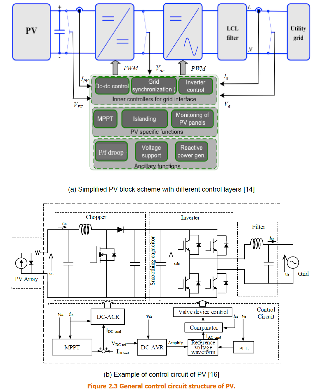
General control structure of a PV inverter. Top: a simplified block scheme with three control layers — inner grid-interface controllers (dc-dc control, grid synchronisation / PLL, inverter control), PV-specific functions (MPPT, islanding, panel monitoring) and ancillary functions (P/f droop, voltage support, reactive power). Bottom: an example control circuit in which MPPT and the DC-ACR set the chopper current while the DC-AVR, PLL, reference-voltage waveform and comparator form the ac-current command that drives the inverter's valve control.
Figure 1 — General control structure of a PV inverter. (a) The simplified block scheme with its three control layers: inner grid-interface controllers (dc–dc control, grid synchronisation / PLL, inverter control), PV-specific functions (MPPT, islanding, panel monitoring) and ancillary functions (P/f droop, voltage support, reactive power). (b) An example control circuit: MPPT and the DC-ACR set the chopper current, while the DC-AVR, PLL, reference-voltage waveform and comparator form the ac-current command that drives the inverter’s valve control.
How to read Figure 1

Trace it from the dc side outward. (1) Start at the PV array. (2) MPPT works out the operating point that extracts the most power. (3) The dc–dc chopper controls the PV-side current and voltage to reach that point. (4) The dc-link capacitor joins the dc–dc and dc–ac stages. (5) The PLL measures the grid (PCC) voltage angle and frequency. (6) The inverter current controller uses that synchronising information to build the ac-current reference. (7) PWM / gate control turns the reference into switching commands for the semiconductors. (8) The ancillary functions can nudge the active- and reactive-current references during grid disturbances.

Section 3

How the control works

Why dwell on the control? Almost all of the inverter’s dynamic behaviour is decided here, so this is the layer your model spends most of its effort on. It is easiest to understand as three nested layers, from the grid inward:

  • Synchronisation layer — the PLL estimates the grid-voltage angle and frequency at the PCC, giving the rest of the control a common reference locked to the grid.
  • Inner current-control layer — forces the inverter’s output current to follow the active- and reactive-current references it is given, quickly and accurately.
  • Outer control layer — decides what those active- and reactive-current references should be, drawing on MPPT, the dc-link voltage, voltage support, frequency response, or whichever grid-code function is active.

A word on a phrase you will meet everywhere: the control makes the inverter current “match the PCC voltage in frequency and phase.” That is precisely true only at unity power factor, where the current is in phase with the voltage and the inverter injects pure active power. When reactive power is required — to support voltage, for instance — the control deliberately shifts the current’s phase relative to the voltage. So “matching phase” is the normal unity-power-factor case, not a universal rule; the later pages on Q(V) and dynamic voltage support rely on exactly this freedom to shift the phase.

Reading Figure 1(b) against those three layers: on the dc side, MPPT sets the maximum-power operating point and the DC-ACR (dc automatic current regulator) drives the PV-side dc current to that reference by switching the chopper. On the ac side, the DC-AVR (dc automatic voltage regulator) watches the dc-link voltage and scales the PLL-derived reference waveform into the ac-current command; the switching is then set by comparing that command against the measured ac current — the valve (gate) control that produces the pulse-width modulation (PWM). In short: MPPT and the DC-ACR shape the dc side, while the DC-AVR, the PLL and the comparator shape the ac side.

Section 4

Average model or switching model?

Why decide this early? It is the first real modelling choice, and getting it right saves enormous effort. It turns on one question — does your study depend on the individual switching, or not?

  • A switching model represents each semiconductor switching event and every PWM pulse explicitly. It shows the real ripple and harmonics — at the cost of a very small time step and slow runs.
  • An average model removes those individual pulses and represents the converter by its fundamental-frequency and control behaviour averaged over each switching period. It runs far faster and is much easier to build and initialise.

An average model can reproduce the relevant low-frequency dynamic behaviour accurately when the study does not depend on switching ripple or individual valve events. That covers most of the work — electromechanical stability, fault ride-through, plant-level control and many EMT dynamic studies. A switching model becomes necessary when the study target is the switching: the harmonic spectrum, switching ripple, EMI compliance, converter losses, semiconductor stress, or detailed filter resonance.

Pick the model to the phenomenon

This is why EMTP® and other EMT tools ship both average-value and detailed switching converter models. Use the average model for stability, control-interaction, ride-through and most dynamic work; reserve the switching model for harmonics, EMI and loss studies, where the switching itself is the object of study.

Section 5

Ancillary functions and grid-code requirements

Why does a grid code enter a modelling page? Because the control is flexible software, a code can ask the inverter to do far more than inject power — and each function you switch on is another block your model may need.

Two documents recur. EU 2016/631 is the European network code “Requirements for Generators” (RfG); IEEE 1547 is the distributed-energy-resource interconnection standard used mainly in North America. Between them they can require support functions such as negative-sequence current injection, reactive current from a power-factor command, a capped reactive-current injection, and reactive current whose level tracks the depth of a voltage dip. Table 1 gathers the most relevant requirements from these two.

Read Table 1 as a high-level teaching summary, not as a substitute for project-specific grid-code compliance. None of these functions is always active in every inverter: what applies depends on the grid code, the connection voltage, the plant size, the country and the project. In modelling, the rule is not to switch on every function, but to include only the ones the study objective and the required grid-code behaviour actually call for.

Table 1 — Ancillary-function requirements for IBG in grid codes and standards (after EU 2016/631 and IEEE 1547-2014/2018). ✓ = required for one or more IBG classes; (✓) = non-mandatory.
RequirementEU 2016/631IEEE 1547-2014IEEE 1547-2018
P(f) (over / under)
Voltage control by reactive power, Q(V)(✓)
Voltage control by active power, P(V)
Synthetic inertia(✓)
ROCOF immunity
Fault ride-through (LV / HV)✓ (LVRT only)(✓)
Inverter internal protections
Anti-islanding detection (passive / active)✓ (ROCOF)
Dynamic voltage support during faults and voltage steps(✓)(✓)
Power oscillation damping(✓)
Black-start capability(✓)
Capability of islanding operation
Automatic disconnection with abnormal voltage
Automatic connection with active-power recovery speed
Constant power at low voltage
Constant power at low frequency

A plain ✓ means one or more classes of IBG must meet the requirement; a bracketed (✓) marks a non-mandatory one. The individual ticks matter less than the direction of travel — each revision asks the inverter to do more. In plain English, the key functions are:

  • P(f) — active power changes as the frequency changes (for example, backing power off when the frequency runs high).
  • Q(V) — reactive power or current changes as the voltage changes, to help hold the voltage.
  • P(V) — active power changes as the voltage changes, usually to manage an over-voltage or a voltage recovery.
  • Synthetic inertia — a fast active-power response designed to imitate the inertial support a spinning machine would give.
  • ROCOF immunity — the inverter must stay connected through an acceptable rate of change of frequency, rather than nuisance-tripping.
  • Fault ride-through (FRT) — the plant must stay connected through specified voltage dips (low-voltage ride-through, LVRT) or swells (high-voltage ride-through, HVRT).
  • Dynamic voltage support — reactive-current injection during a voltage disturbance to prop the voltage up.
  • Power oscillation damping (POD) — active- or reactive-power modulation that damps power-system oscillations.
  • Black start — the ability to energise a dead section of network without an external grid voltage to lock onto.

Section 6

Inverter protection: internal versus external

Why separate the two? A plant that “rides through” on paper can actually trip in reality once its protection is added, so the model has to get the split right. The division is by purpose, not by location. The simple rule:

  • Internal protection protects the converter hardware. Examples: dc over-voltage, dc over-current, the semiconductor current limit, and thermal or current-rate limits. It is applied by the manufacturer and need not follow the protection-relay standards (IEC TC 95).
  • External (interface) protection protects the network interface and decides whether the plant should stay connected to the grid. Examples: over/under-voltage, over/under-frequency, ROCOF, vector shift (vector jump), loss-of-mains and anti-islanding.
Why the split matters for modelling

An external/interface protection function can physically live inside the very same inverter controller as the internal protection — but it should be modelled separately, because its settings are project- and grid-code-dependent and change from one connection to the next. Keeping it as its own block lets you change those settings without touching the inverter model. Internal protections, by contrast, are usually built straight into the inverter model and do not change the plant’s capabilities.

Section 7

Internal protection

Internal (also called generator) protection exists to keep the inverter hardware from being damaged — it has nothing to do with the network interface. Typical examples:

  • Reducing the maximum inverter current when the dc voltage exceeds a limit.
  • Limiting the rate of change of inverter current after a fault.
  • Limiting the total reactive current.
  • Manual field shutdown with an emergency stop, and PV-field insulation detection.
  • DC over-current and dc over-voltage protection, together with ac over/under-voltage and over/under-frequency protection.

Two of these — the current rate-of-change limit after a fault and the total-reactive-current limit — are really control functions. Because they also act protectively, the source brochure treats them as internal protection; in a model they may sit in either the control or the protection block, as long as they act.

Section 8

External (interface) protection

Why it earns its own section: interface protection is where the plant decides, in real time, whether to stay with the grid or drop off — and getting that decision wrong is either a safety hazard or a nuisance trip. Its purpose is to detect uncontrolled local islanding and disconnect (loss-of-mains protection), to reduce plant output so as to prevent a network over-voltage or over-frequency, and to help the system reach a controlled state during voltage or frequency excursions. It is generally built from combinations of over/under-voltage and over/under-frequency elements.

Loss-of-mains and anti-islanding

Islanding happens when a local section of network stays energised by the IBG after it has been disconnected from the main grid. That is dangerous: it endangers personnel working on lines believed to be dead, upsets protection coordination, complicates safe reconnection, and degrades power quality. Detection comes in two styles. Passive methods watch a measured quantity — voltage, frequency, ROCOF or vector jump — for the tell-tale change when the grid disappears. Active methods deliberately perturb the inverter’s output a little and look for the abnormal response that only an island would give.

Interface protection has to balance two opposing demands: trip quickly for a genuine local island, yet stay connected through a wider system disturbance where the grid code requires ride-through. It is just as important to say what it is not for. It does not clear faults inside the generating plant — that belongs to other relays coordinated with the network protection — and it does not protect the unit against incidents on the network, for which the unit must have an appropriate immunity level. Disconnection should be fast and reliable for local faults, but must not trip for wide-area disturbances unless voltage and frequency stay far from normal for a relatively long time. Sensitivity and operating times therefore depend on the network and its protection; CIGRE TB 613 and TB 421 give good overviews.

Section 9

Primary energy sources

Why the source matters at all: the same inverter interface does not mean the same plant behaviour — what sits behind the inverter sets the limits of what it can deliver. Renewable energy sources (RES) mostly reach the grid through an inverter, a converter from dc to single- or poly-phase ac. IBGs are 100% of PV and a growing share of wind (full-converter and DFIG units run well above 4 MW), and appear in ORC plants and micro-turbines too. The inverter technology is broadly similar across devices, but the prime mover differs, and that shapes the control and the response the plant can achieve.

Table 2 classifies the technologies by primary source, whether there is a rotating prime mover, and whether a rotating machine is used as the generator. As you read it, ask two things: is the primary source rotating or non-rotating (which sets how much stored energy is available and how fast the plant can respond), and is there a rotating generator (which adds mechanical dynamics that can couple into the electrical controls)? In many grid dynamic studies, though, the inverter control still dominates what the terminals actually do.

Table 2 — Classification of inverter-based generator technologies by primary source, prime mover and generator type.
TechnologyPrimary sourcePrime mover (rotating)Rotating machine as generator
Wind energy conversion systemWindYesYes
Micro-turbineDiesel or gasYesYes
ORC (with or without micro-turbine)Waste heatYesYes
Fuel cellHydrogenNoNo (optionally yes)
PhotovoltaicsSunNoNo
Superconducting magnetic energy storageStorageNoNo
Battery energy storageStorageNoNo
FlywheelStorageYesYes
Variable-speed hydro (voltage-source converter or cycloconverter)WaterYesYes

The generic interface takes one of a few forms: a dc source (PV, battery or fuel cell) straight into the inverter; an ac generator rectified to dc and then inverted (a micro-turbine or a full-converter WTG); or the DFIG arrangement, where the stator connects directly to the grid and only the rotor passes through a converter. Why the source still changes the behaviour:

  • PV has no rotating inertia and normally no stored energy, so it responds almost instantly but cannot support a falling frequency unless it is curtailed or paired with storage.
  • Battery storage can respond very fast — provided the state of charge and the converter rating allow it.
  • Full-converter wind has real mechanical inertia behind the converter, but the grid only sees what the converter control chooses to pass through.
  • DFIG is different again: its stator is connected directly to the grid while only the rotor goes through a converter, so it is not identical to a full-converter plant.
  • Fuel cells, micro-turbines and ORC units have slower primary-energy dynamics, set by chemistry or a thermal cycle.
The one thing to remember

The grid does not directly see the sun, the wind, the battery or the turbine. It sees the behaviour imposed by the converter and its controls — constrained by the primary energy that happens to be available.

Section 10

Why the primary source is often neglected

Why this is worth stating plainly: knowing when you may simplify the source — and when you may not — keeps the model as small as the study allows, and no smaller. Unlike conventional thermal or hydro machines, where the generator dynamics dominate, an IBG’s behaviour is set mainly by its electrical control model — the generator and its electronic interface. For short-term, transient and dynamic studies at the grid terminals, the primary-source detail loses importance and the source can be treated as a stiff dc source, which usefully simplifies the analysis.

A practical rule

For short-duration electrical disturbances — voltage dips, current limiting, PLL response, fault ride-through — the inverter control is the dominant model and the primary source can be a stiff dc source. For longer-duration studies — frequency response, energy recovery, storage depletion, wind-speed recovery, curtailed operation — the primary source and the energy actually available may need to be represented. This is exactly the distinction the later frequency-stability and long-term voltage-stability pages build on.

The source still constrains the capabilities. Frequency response, for instance, is fast in the inverter yet may be ramp-limited by a slower primary source, so the mid- and long-term behaviour depends on the source type. The practical stance is to treat an IBG as two components — inverter and generator — each with its own frequency-control requirements and response.

Section 11

From characteristics to model functionalities

Here is the practical output of the whole page — the point where “how an inverter works” becomes “what blocks my model needs.” Every characteristic above maps to a functionality, and the functionalities fall into three groups:

  • Control functions decide what the inverter tries to do — synchronise, regulate current, track maximum power, hold the dc voltage.
  • Protection functions decide when the inverter limits, blocks, trips or changes mode to protect the equipment or the network.
  • Capability functions define what the inverter is able or required to provide under a grid code or a project specification.

Table 3 lists them under those three headings.

Table 3 — Functionalities of an IBG model, grouped as Control, Protection and Capability.
CategoryFunctionality
ControlDC source control
ControlCurrent control
ControlPLL
ControlMPPT
ProtectionReduction of maximum inverter current when the dc voltage exceeds a limit
ProtectionLimitation of inverter current’s rate of change after a fault
ProtectionCurrent limit
ProtectionDC over-voltage protection
ProtectionOver / under-voltage protection
ProtectionOver / under-frequency protection
ProtectionProtection for detecting a balanced fault
ProtectionProtection for detecting an unbalanced short-circuit fault
ProtectionProtection for detecting a single-line-to-ground fault
ProtectionROCOF tripping (disconnect above a set Hz/s)
ProtectionVector jump
ProtectionTransfer trip
ProtectionAnti-islanding active detection method
CapabilityP(f) control (over / under frequency)
CapabilityVoltage control by reactive power, Q(V)
CapabilityVoltage control by active power, P(V)
CapabilitySynthetic inertia
CapabilityROCOF immunity
CapabilityFault ride-through (LV / HV)
CapabilityActive behaviour during fast voltage variations
CapabilityPower oscillation damping (POD)

These three groups are exactly what the later pages use to decide the minimum model detail for each study type — together with the average-versus-switching choice and the EMT-versus-RMS choice.

A model-selection checklist

For a dynamic study, do not start by asking whether the plant is PV, wind or battery. Start by asking:

  • 1. Which grid phenomenon am I studying?
  • 2. Which inverter control functions affect that phenomenon?
  • 3. Which protection functions might operate?
  • 4. Which grid-code capabilities must be represented?
  • 5. Is an average model enough, or does the study need switching detail?

Common mistakes

Common mistakes

The traps that most often distort an inverter model — each the flip side of a section above:

Five traps to avoid
  • Treating an average-value model as suitable for a harmonic, ripple or EMI study.
  • Forgetting that reactive-current support changes the active / reactive current priority under the current limit.
  • Assuming every grid-code function — P(f), Q(V), synthetic inertia, ride-through, POD — is present in every inverter.
  • Confusing internal converter protection with the interface protection that coordinates with the network.
  • Ignoring the primary-source limits — irradiance, rotor speed, state of charge — in frequency or energy studies.

Section 12

Key points

The inverter is the interface — and, for dynamics, the story
  • What the inverter does — it converts the source’s dc into ac and, via the PLL, injects a current locked to the PCC voltage (in phase for pure active power; phase-shifted when reactive support is asked for).
  • Topology matters but generalises — two-level, multilevel, H-bridge and NPC share enough that one family of models serves PV, wind and storage.
  • Average models are normally enough — they capture the low-frequency dynamics for stability, ride-through and control studies.
  • Switching models are for the switching itself — harmonics, ripple, EMI, losses, device stress, filter resonance.
  • Grid-code functions are represented only when relevant — P(f), Q(V), P(V), synthetic inertia, ROCOF immunity, ride-through, POD, black start are optional unless a study (or a code) depends on them.
  • Internal and interface protection are separated — internal protects the converter; interface protects and coordinates with the network, and is modelled as its own block so settings can change.
  • The primary source can often be simplified — neglected for short-term dynamics, but represented for longer-term frequency and energy-recovery studies, where it constrains the response.
  • Three modelling categories — Control, Protection and Capability — are what every later study draws on.

For how these behaviours differ from a synchronous machine, see the companion guide on the characteristics of inverter-based generation; for the protection detail, the renewable-converter protection system; and for the model-type choice, EMT versus RMS.

References

References

The CIGRE technical brochure on modelling inverter-based generation is the primary reference for this page; the EU network code and IEEE 1547 are the sources for the ancillary-function requirements; and the EMTP® documentation is the reference for the average-value and switching converter models.

  1. CIGRE Working Group, Modelling of Inverter-Based Generation for Power System Dynamic Studies. CIGRE Technical Brochure.
  2. Commission Regulation (EU) 2016/631, Establishing a Network Code on Requirements for Grid Connection of Generators (RfG). European Commission.
  3. IEEE Std 1547-2018, Standard for Interconnection and Interoperability of Distributed Energy Resources with Associated Electric Power Systems Interfaces. IEEE.
  4. EMTP®, Renewable and Inverter-Based Generation — Average-Value and Detailed Converter Model Documentation. Powersys / EMTP®.

Twelve-Part Technical Series

Modelling Inverter-Based Generation

A twelve-part guide to modelling inverter-based generation — from device characteristics and the RMS and EMT model families, through model adequacy, validation and large-scale wide-area EMT, to frequency, voltage and small-signal stability studies.

Part 2 Reading now

Inverter Characteristics for IBG Modelling

Inside the inverter: topology, the dc/ac chain, control, protection and the capability functions grid codes require.

Series progress 2 of 12



