United Kingdom
Click to view details
UK Registered Office
Address18 Canberra Road
Gretna, Dumfriesshire
Scotland
DG16 5DP
Gretna, Dumfriesshire
Scotland
DG16 5DP
Text can be selected and copied.
APS provides specialist testing and diagnostic assessment of MV and HV cable systems, including route location, cable identification, sheath integrity testing, fault location, partial discharge assessment, VLF withstand testing, tan delta diagnostics, and bonding and termination condition review — assessing the cable system as a complete assembly rather than an isolated cable length.
Specialist MV and HV cable diagnostics, route tracing and fault location — route location and cable identification, VLF withstand testing, tan delta diagnostics, partial discharge assessment, sheath integrity testing and bonding verification, aligned with IEC 60502 series, IEEE 400 series and CIGRE guidance.
Cable systems are exposed to electrical, thermal, mechanical and environmental stress throughout their life. Defects may be introduced during installation, jointing, termination, pulling, backfilling, bonding or commissioning, while ageing mechanisms develop later through moisture ingress, insulation deterioration, sheath damage, partial discharge activity, thermal cycling or localised mechanical impact. The consequences of an in-service cable failure range from extended outage and equipment damage to safety risk, costly emergency repair and regulatory scrutiny.
A structured cable-testing programme confirms whether the system is suitable for energisation, continued service, repair or replacement. The programme can include route location and cable identification before excavation, fault location after an outage or sheath damage event, diagnostic testing to assess insulation condition, withstand testing before energisation, sheath integrity checks to confirm the metallic screen is undamaged, and bonding verification to confirm the installation is correctly configured for load and fault conditions.
APS combines practical site testing, diagnostic interpretation and engineering review to assess cable condition as a complete system rather than an isolated cable length — including the insulation, metallic sheath or screen, joints, terminations, bonding arrangement, route condition, earthing interface and installation environment. Test results are interpreted against applicable IEC, IEEE and CIGRE acceptance criteria, manufacturer guidance, baseline data and site-specific conditions to support clear engineering conclusions rather than pass/fail numbers alone.
Cable route location and identification is a key activity before excavation, repair, diversion, fault investigation or new construction in the vicinity of existing cables. APS supports the identification of underground routes, cable position, likely depth profile, cable sections and route features so that intrusive works can be planned with reduced risk — particularly where drawings are incomplete, records are outdated, cable diversions are planned, buried services are congested, or a specific cable must be positively identified before switching, cutting or repair.
Route tracing uses electromagnetic induction and direct signal injection techniques to trace the path of a cable from a known reference point. Depth profiling provides an estimate of burial depth at measured intervals along the route, supporting excavation planning and enabling the detection of depth anomalies that may indicate previous reinstatement, concrete encasement, route deviation or a buried joint. Cable identification confirms which cable in a congested duct run, joint bay or termination chamber corresponds to a known circuit, using a signal injected at one end and detected with a clamp or probe at the other end without interrupting supply.
The technique is most valuable at substations, industrial plants, EV charging infrastructure, renewable energy projects, data centres and urban cable corridors — any environment where incomplete or uncertain cable records increase the risk of accidental cable damage, incorrect circuit identification or unsafe working. A confirmed route and verified identity before a switchgear operation or excavation is a straightforward intervention that significantly reduces the risk of a costly or dangerous mistake.
Cable fault location moves from fault confirmation to approximate pre-location and then to accurate pinpointing. Faults may be low-resistance, high-resistance, intermittent, sheath-related or insulation-related, and a staged approach is normally required: initial confirmation using insulation resistance and sheath integrity checks, reflectometry-based pre-location, route correlation, and final pinpointing where site conditions and access allow.
Time-domain reflectometry (TDR) is used for low-resistance fault pre-location, sending a pulse along the cable and measuring the reflected waveform from discontinuities, including open circuits, short circuits, low-resistance earth faults, splices, joints and high-impedance changes in the cable geometry. The time-of-flight of the reflection determines the distance to the fault, which must then be correlated against the known cable route to establish a physical location for excavation planning.
Arc-reflection and impulse-current methods are used for high-resistance faults that TDR cannot resolve directly. These techniques apply a voltage surge to the faulted cable to condition or break down the fault resistance to the point where the location can be identified using surge-correlation techniques. Final pinpointing uses a surge generator and an electromagnetic or acoustic detector — the acoustic receiver detects the sound of the surge discharge at the precise fault location, allowing the excavation to be targeted accurately on the ground surface.
Sheath fault location follows a similar staged approach. A DC voltage is applied across the sheath; the leakage current and decay characteristics identify whether a fault is present, and sectioning and differential current techniques narrow the fault position to a location that can be confirmed without unnecessary excavation.
VLF, tan delta and partial discharge diagnostics give a far stronger basis for engineering judgement than a simple pass/fail withstand test. A cable that passes a withstand test has demonstrated that it can survive a controlled overvoltage for a specified time — but it does not reveal insulation condition, whether moisture ingress is developing, whether a joint has been incorrectly assembled, or whether partial discharge activity is eroding the insulation at a localised interface. Diagnostic testing reveals these conditions.
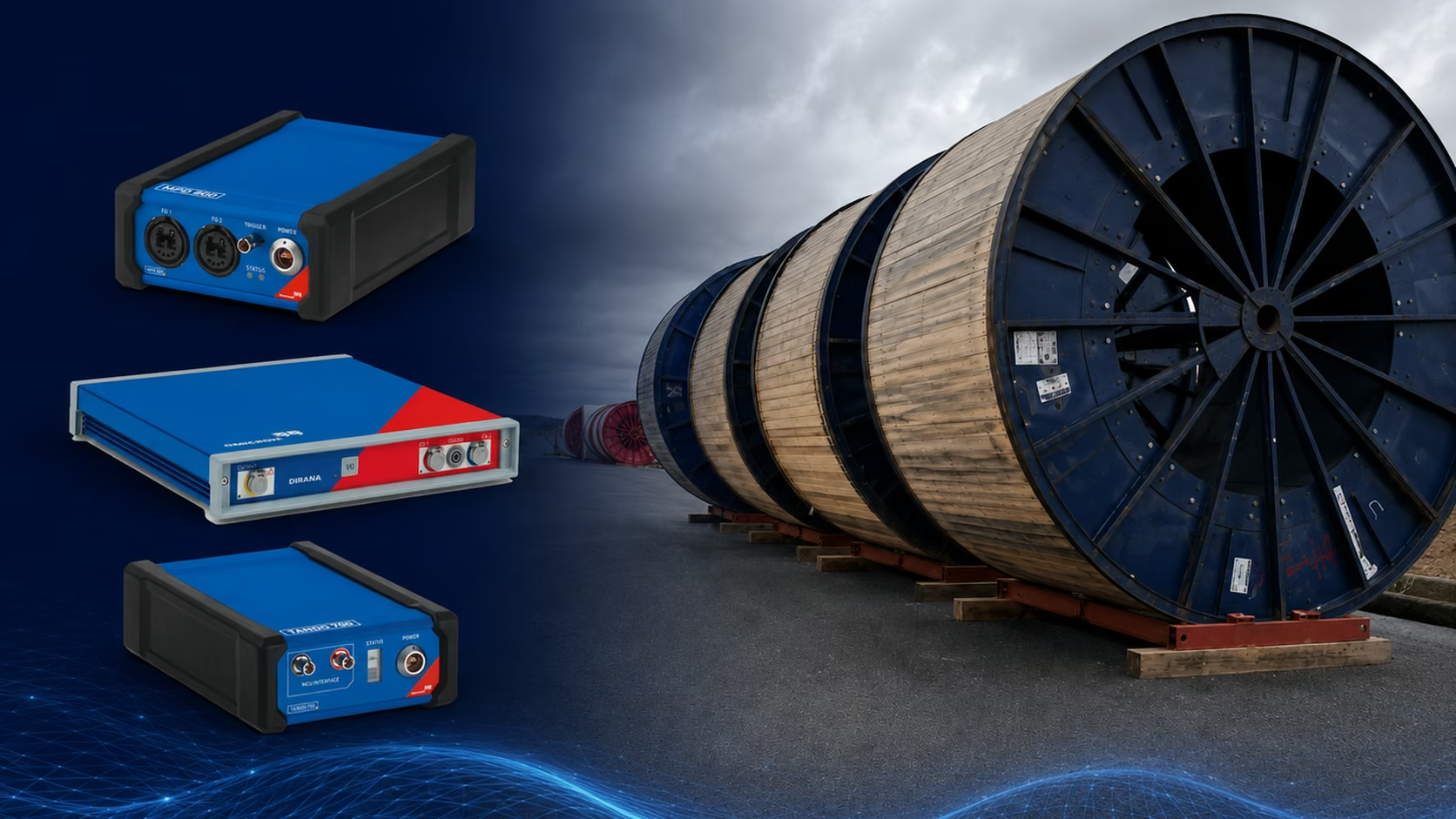
VLF withstand testing applies a sinusoidal voltage at very low frequency (typically 0.1 Hz). At VLF frequency, the charging current is approximately 500 times lower than at power frequency, making it practical to energise long cable circuits with portable equipment. VLF withstand testing is widely used for pre-energisation acceptance of new MV cable installations and for in-service testing during planned outages, and can be combined with tan delta and partial discharge measurement to extend the information obtained from a single test event.
Tan delta (dielectric loss angle) measurement assesses the dielectric losses in the cable insulation across the whole circuit. An increasing tan delta with voltage is associated with moisture ingress, aged insulation or water tree development. Periodic tan delta trending over successive outages provides an insulation ageing index that supports condition-based maintenance decisions — identifying cables approaching end of life before they fail in service.
Partial discharge testing localises defects within the cable system, particularly at joints, terminations and insulation interfaces where the electric field stress is highest. Phase-resolved partial discharge (PRPD) patterns allow PD sources to be characterised and distinguished from external noise. Combined with time-domain reflectometry, PD signals can be localised to a specific length along the cable, enabling targeted investigation and repair rather than full replacement.
The test scope is tailored to the project requirement and may cover a single activity — route location before excavation, fault pinpointing after an outage — or a comprehensive diagnostic programme for commissioning acceptance or condition assessment.
Testing and interpretation are aligned with recognised IEC, IEEE and CIGRE frameworks. Where a project specifies a particular standard, APS tests and reports against the framework relevant to the cable type, voltage class, accessory design and manufacturer guidance.
These services apply across the full cable-system lifecycle, from route confirmation and pre-energisation testing for new installations through condition monitoring and fault investigation for in-service assets.
The scope of documentation is agreed with the client at the outset and adapted to the purpose of the testing — whether a route survey before excavation, a fault location investigation or a comprehensive pre-energisation commissioning record.
The objective of APS cable testing and diagnostics is to identify cable-system defects before they lead to failure, outage, safety risk or costly emergency repair. The distinction between a simple withstand test and a full diagnostic programme matters in practice: a cable that passes a withstand test has demonstrated survivability under a controlled overvoltage condition, but it has not revealed whether the insulation is ageing, whether moisture is tracking through a water tree network, whether a joint has been misassembled, or whether partial discharge activity is eroding the insulation at a localised interface. These are the conditions that produce the next failure.
Modern cable asset management has moved toward diagnostic techniques — tan delta trending, partial discharge localisation, sheath testing after every intrusive event — precisely because they reveal the state of the insulation system rather than simply confirming it can survive one more overvoltage event. A condition assessment programme that combines these techniques with engineering interpretation gives clients an insulation ageing index, a joint and termination health review, and a risk-ranked prioritisation for maintenance, repair and replacement that no simple test schedule can provide.
For fault investigations, the combination of TDR pre-location, route correlation and acoustic pinpointing reduces the area requiring excavation to a targeted length — often a matter of metres — rather than exposing the full cable route. This reduces cost, duration, reinstatement risk and the probability of inadvertently damaging the cable or adjacent services during the investigation.
By combining route location, fault investigation, sheath testing, VLF withstand, tan delta diagnostics, partial discharge assessment and engineering interpretation, APS gives clients a practical, standards-aligned understanding of cable condition and reliability — supporting safer excavation, more targeted repairs, improved commissioning confidence, reduced outage time and better asset-management decisions.