Insulation Coordination & Overvoltages

Types of Overvoltages

Overvoltages in power systems are classified by their duration, wave shape, frequency content and physical origin, because each type stresses insulation differently and therefore demands a different study approach, modelling assumptions and insulation-coordination checks. Following IEC 60071-1, the principal classes are temporary overvoltages (TOV), slow-front overvoltages (SFO), fast-front overvoltages (FFO) and very-fast-front overvoltages (VFFO) — broadly tied to low-frequency system behaviour, switching, lightning and GIS / very-fast switching respectively. Identifying the overvoltage type is the first step in choosing the right insulation level, surge-protection arrangement and EMTP modelling approach.

Reading time ≈ 24 min · APS technical note

An overvoltage is any voltage — between a phase and earth, or between phases — whose peak rises above the crest of the highest voltage for which the equipment is designed. Overvoltages in power systems are classified according to their duration, wave shape, frequency content and physical origin. This classification matters because each type of overvoltage stresses equipment in a different way, and therefore requires a different study approach, different modelling assumptions and different insulation-coordination checks. The correct identification of the overvoltage type is the first step in selecting the appropriate insulation level, surge-protection arrangement and EMTP modelling approach.

Temporary overvoltages are generally associated with power-frequency or low-frequency system behaviour. Slow-front overvoltages are mainly associated with switching operations. Fast-front overvoltages are mainly associated with lightning. Very-fast-front overvoltages are mainly associated with GIS switching, short busbars and some vacuum circuit-breaker operations.

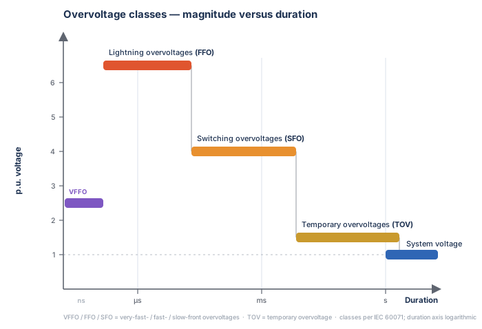
Overvoltage classes plotted as per-unit voltage versus duration on a logarithmic time axis: very-fast-front (VFFO) at about 2.5 p.u. and nanoseconds, lightning fast-front (FFO) highest at about 6 p.u. and microseconds, switching slow-front (SFO) about 4 p.u. over microseconds to milliseconds, temporary overvoltage (TOV) about 1.5 p.u. over milliseconds to seconds, and the continuous system voltage at 1 p.u.
Figure 1 — Types of overvoltages — per-unit voltage versus duration. The shorter the duration of an overvoltage, the higher its possible peak: temporary overvoltages have lower peaks but long duration, while lightning and very-fast-front overvoltages are brief yet can impose severe insulation stress through their steep front and high peak.
Main takeaway
  1. Temporary overvoltages (TOV) — low-frequency, long-duration stresses, mostly power-frequency system behaviour.
  2. Slow-front overvoltages (SFO) — switching-related, microsecond-to-millisecond fronts.
  3. Fast-front overvoltages (FFO) — mainly lightning, short fronts and high peaks.
  4. Very-fast-front overvoltages (VFFO) — nanosecond fronts with MHz content, mainly GIS, short busbars and very fast switching.
Abbreviations used on this page
01TOV
Temporary overvoltage — low-frequency overvoltage at or near power frequency.
02SFO
Slow-front overvoltage — switching overvoltage (μs–ms front).
03FFO
Fast-front overvoltage — mainly lightning (sub-μs to μs front).
04VFFO
Very-fast-front overvoltage — nanosecond front, MHz content (GIS).
05p.u.
Per unit — voltage expressed relative to a chosen base (often the peak phase-to-earth voltage).
06GIS / AIS
Gas-insulated / air-insulated switchgear.
07Earth-fault factor
Ratio of the healthy-phase voltage during an earth fault to the pre-fault voltage — the headline driver of TOV.
08Over-fluxing
Core saturation from an excessive volts-per-hertz (\(V/f\)) ratio in transformers and reactors.
09LIWL / SIWL
Lightning- / switching-impulse withstand level of the insulation.
10IEC
International Electrotechnical Commission — publisher of the insulation-coordination standards (e.g. IEC 60071-1) used here.
11EHV / UHV
Extra-high voltage / ultra-high voltage — the highest transmission-voltage tiers.
12Range I / II
IEC voltage ranges by highest equipment voltage \(U_m\): Range I is \(U_m \le 245\) kV, Range II is \(U_m > 245\) kV.
13EMT / EMTP
Electromagnetic-transient (program) — time-domain simulation used for transient-overvoltage studies.

Section 1

Overvoltage classification (IEC 60071-1)

IEC 60071-1 classifies voltage stresses into low-frequency voltages and transient overvoltages. Low-frequency voltages include the continuous operating voltage and temporary overvoltages. Transient overvoltages include slow-front, fast-front and very-fast-front overvoltages. The standard also recognises a combined overvoltage class, but the five listed above are the principal ones used in practice.

The main difference between the classes is the time scale of the phenomenon. Temporary overvoltages may last from several cycles to many seconds. Slow-front overvoltages normally occur in the microsecond-to-millisecond range. Fast-front overvoltages have much shorter front times and are typically associated with lightning. Very-fast-front overvoltages have extremely steep fronts and contain high-frequency components in the MHz range.

Reading an impulse shape — front time and time to half-value

Transient overvoltage shapes are described by two times measured from the start of the surge. The front time (\(T_1\), or \(T_p\) for a switching impulse) is the time taken to reach the crest; the time to half-value (\(T_2\)) is the time for the tail to fall back to half the crest. The shorthand “1.2/50 μs”, for example, means a 1.2 μs front time and a 50 μs time to half-value. The same two parameters describe every transient class below — only their magnitudes change.

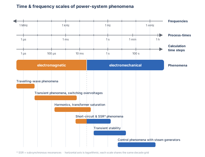
Aligned logarithmic scales of characteristic frequency, process time and simulation time step for power-system phenomena, split into electromagnetic (fast) and electromechanical (slow) regions, with study types from travelling-wave phenomena at microseconds to control phenomena at hundreds of seconds.
Figure 2 — Time and frequency scales of power-system phenomena. The overvoltage classes occupy the fast (electromagnetic) end of this map; the time scale of the event fixes the frequency range that the model must represent and therefore the required simulation time step.
IEC 60071-1 table of classes and shapes of overvoltages. Columns: continuous, temporary, slow-front, fast-front and very-fast-front. Rows give the voltage or overvoltage shapes, the range of shapes, the standard voltage shapes and the standard withstand tests, including 48 to 62 hertz 60-second power-frequency test, 250/2500 microsecond switching impulse and 1.2/50 microsecond lightning impulse.
Table 1. Classes and shapes of overvoltages, standard voltage shapes and standard withstand tests (after IEC 60071-1). There is no standardised shape or withstand test for the continuous and very-fast-front classes.
Takeaway

The shorter the duration, the higher the possible peak magnitude. The class fixes the relevant frequency range, the standard test (power-frequency, switching impulse or lightning impulse) and the modelling detail needed.

Section 2

Continuous power-frequency voltage

Continuous power-frequency voltage is the normal operating voltage of the system. It is not itself a transient overvoltage, but it is the reference condition for insulation coordination. For standard AC systems it has a frequency of 50 Hz or 60 Hz and is treated as a long-duration condition, with duration \(T_t \ge 3600\) s.

Continuous voltage matters because the insulation must withstand it permanently during normal operation. It also provides the base from which temporary and transient overvoltages are commonly expressed in per unit.

Section 3

Temporary overvoltages (TOV)

Temporary overvoltages are low-frequency overvoltages at or close to power frequency, usually longer in duration than switching or lightning overvoltages. The typical range of shapes is a frequency of 10 Hz to 500 Hz and a duration \(T_t\) from 0.03 s to 3600 s. The standard short-duration power-frequency withstand test is generally based on 48 Hz to 62 Hz and a duration of 60 s, unless the relevant equipment standard specifies otherwise.

The word temporary describes the duration, not the severity — a sustained power-frequency overvoltage of only about 1.3–1.5 p.u. can overheat a surge arrester or saturate a transformer core in a way that a far higher but microsecond-long impulse never would. Temporary overvoltages are important because they set the power-frequency insulation stress, and because they govern the energy capability and thermal withstand of metal-oxide surge arresters (MOSA) — the zinc-oxide, gapless arresters that protect equipment by conducting heavily only above a threshold voltage and so clamping the overvoltage to a known protective level. An arrester may be correctly rated for lightning or switching impulses yet still be overstressed if the system TOV is too high or lasts too long. TOVs can also stress transformers and shunt reactors through over-fluxing: when the volts-per-hertz (\(V/f\)) ratio becomes too high, the core flux becomes excessive, raising the magnetising current and causing heating, vibration and possible damage if the condition is severe or sustained.

The earth-fault factor — the headline TOV case

The classic source of temporary overvoltage is a single-line-to-earth fault: the voltage on the healthy phases rises by the earth-fault factor, which depends on the system earthing (the \(X_0/X_1\) and \(R_0/X_1\) ratios). It is typically up to about 1.4 in effectively earthed systems and can approach \(\sqrt{3}\) in isolated or resonant-earthed systems. The earth-fault factor, the fault duration and the protection clearing time together set the TOV stress on equipment and arresters.

Typical sources of temporary overvoltage include load rejection, transformer energisation, parallel-line resonance, uneven circuit-breaker pole operation, backfeeding, fault application and fault clearing. Ferroresonance is a special form of temporary overvoltage involving the interaction of nonlinear inductance, capacitance, low damping and system switching; because it has its own modelling requirements and can produce complex sustained oscillations, it is usually treated as a separate study topic.

Section 4

Slow-front overvoltages (SFO)

Slow-front overvoltages are transient overvoltages mainly associated with switching events; their wavefront is slower than a lightning impulse, so they are usually called switching overvoltages. The typical range of shapes is a front time \(20\) μs \(< T_p \le 5000\) μs and a time to half-value \(T_2 \le 20\) ms. The standard switching impulse is defined by a front time \(T_p = 250\) μs and a time to half-value \(T_2 = 2500\) μs. The two terms are not perfectly interchangeable, though: “switching overvoltage” names the cause, while “slow-front overvoltage” names the wave shape. Most switching produces slow-front waves, but some switching events — vacuum-breaker operation, or switching inside a GIS — also generate fast- and very-fast-front components, so one switching operation can excite more than one class at once.

Slow-front overvoltages influence the required withstand voltage of equipment, the air clearances, the insulation design of transmission lines and the energy duty of surge arresters. For lower transmission voltages — Range I systems with highest equipment voltage up to 245 kV — switching overvoltages are generally less onerous than lightning. For EHV and UHV (Range II) systems they become much more important and can become the controlling factor for insulation design.

SFO studies should consider the network configurations and switching conditions that produce the highest overvoltages — usually line energisation and re-energisation, line fault application and clearing, capacitive-load closing and inductive-load opening. Line re-energisation can be especially severe when trapped charge remains on the line. Trapped charge is the DC voltage left on the line’s capacitance after the breaker opens, which on an unloaded line can persist for tens to hundreds of milliseconds; if the breaker recloses onto it, the voltage difference across the contacts can create high switching overvoltages.

Re-ignition and restrike

During capacitive or inductive current switching, the breaker gap may break down again after current interruption because the rate of rise of recovery voltage exceeds the dielectric recovery. Measured from current interruption at a current zero, a breakdown that occurs within a quarter cycle of power frequency is a re-ignition; one that occurs a quarter cycle or more after final interruption is a restrike (terminology per IEC 62271-100 / IEEE C37). Restrike can generate high slow-front overvoltages and may introduce higher-frequency components depending on the circuit. For Range I equipment a specific switching-impulse withstand value may not be specified; in that case the insulation-coordination objective and acceptance criteria should be defined before the study.

Section 5

Fast-front overvoltages (FFO)

Fast-front overvoltages are mainly produced by lightning strokes. Their magnitude can be much higher than other types, although their duration is much shorter. The typical range of shapes is a front time \(0.1\) μs \(< T_1 \le 20\) μs and a time to half-value \(T_2 \le 300\) μs. The standard lightning impulse is defined by a front time \(T_1 = 1.2\) μs and a time to half-value \(T_2 = 50\) μs.

Fast-front overvoltages are critical for all voltage levels, and especially for substations connected to overhead lines, exposed transmission lines, line entrances, transformers, reactors, GIS/AIS interfaces and equipment near surge-entry points. FFO studies assess the risk of equipment failure, select the required lightning-impulse withstand level and evaluate the effectiveness of metal-oxide surge arresters — whose configuration, location and rating strongly influence the voltage that appears across protected equipment.

FFO studies also consider tower earthing, shielding performance, back flashover, direct strokes, line surge propagation and station performance. High tower-footing resistance increases the probability of back flashover and therefore the lightning stress entering the system. Although lightning is the main source of FFO, some switching devices can also create fast-front transients: vacuum circuit-breakers, for example, can produce steep fronts through current chopping and restrike — in fact these multiple re-ignition transients often straddle the boundary between the fast-front and very-fast-front classes.

Section 6

Very-fast-front overvoltages (VFFO)

Very-fast-front overvoltages have extremely steep fronts and very high-frequency content. They are mainly associated with gas-insulated substations, short busbar sections, disconnector operation, internal GIS flashover and some vacuum circuit-breaker cases. The typical range of shapes is a front time \(3\) ns \(< T_f \le 100\) ns, with a high-frequency component \(0.3\) MHz \(< f_1 < 100\) MHz and a lower-frequency oscillatory component \(30\) kHz \(< f_2 < 300\) kHz. The practical distinction from a fast-front (lightning) overvoltage is the front itself: a VFFO front is measured in nanoseconds rather than microseconds — perhaps a thousand times steeper — so its energy sits in the MHz band, its shape is fixed by the metre-scale geometry inside the GIS rather than by the line, and it rises too quickly for a conventional surge arrester to follow and clamp.

VFFOs are important for GIS insulation coordination, internal-flashover assessment, enclosure transient voltages and high-touch-voltage risk. Because the physical dimensions in GIS are short and the damping is low, very steep travelling waves — voltage and current surges that propagate along a line or busbar at close to the speed of light and partially reflect at every impedance discontinuity, such as an open breaker, a busbar junction or a transformer terminal — can be created and reflected many times within the enclosure and connected equipment.

VFFOs typically appear during GIS switching, especially disconnector pre-strikes and restrikes; SF6 circuit-breaker re-ignition can also produce them. Vacuum circuit-breakers in medium-voltage systems can impose similar high-frequency stresses, particularly with current chopping and multiple restrikes. Point-on-wave (controlled) switching can reduce the risk of some VFFOs by controlling the switching instant, but analysis is still required because control malfunction, abnormal conditions or unexpected switching sequences may still produce severe high-frequency overvoltages.

Section 7

Which type matters — types of study

The importance of each overvoltage type depends on the system voltage level and the event being assessed. For Range I levels (highest equipment voltage up to 245 kV), fast-front lightning overvoltages are usually the governing transient and must be carefully considered, and a switching-impulse withstand is often not separately specified — the switching stress is generally covered by the power-frequency and lightning-impulse tests rather than being negligible.

For higher voltages, slow-front overvoltages become increasingly important; in EHV and UHV (Range II) systems switching overvoltages can become the main factor governing insulation design, which is the engineering basis for specifying a separate switching-impulse withstand only in Range II. Lightning remains relevant in Range II, but with the larger clearances and coordinated surge protection it is often less controlling than switching. Temporary overvoltages must be studied at all voltage levels, because they influence power-frequency withstand, surge-arrester duty, transformer and reactor over-fluxing and general insulation stress.

The class also fixes the simulation tool. Temporary overvoltages, being at or near power frequency, can often be assessed with RMS / phasor or dynamic tools, and only need an electromagnetic-transient (EMT) model when waveform detail or harmonic resonance matters. Slow-, fast- and very-fast-front overvoltages are genuine wide-band transients and must be studied in a time-domain EMT program (EMTP-type software). Very-fast-front studies are the most demanding: the nanosecond fronts force a very small simulation time step — of the order of nanoseconds — together with a model that captures the metre-scale GIS geometry.

Table 2 maps common network events to the classes they generate. Several rows carry more than one tick, because a single physical event often launches stresses in more than one class at once — energising a line produces a slow-front switching transient but also short-duration fast-front components at the wavefronts, and a fault both raises a power-frequency TOV on the healthy phases and injects a slow-front transient when it is cleared. The table shows where each event can contribute, not a single exclusive label.

Table 2 — Network events and the overvoltage classes they most commonly generate.
EventTOVSFOFFOVFFO
Load rejection
Transformer energisation
Parallel-line resonance
Uneven breaker poles
Backfeeding
Line fault application
Fault clearing
Line energisation
Line re-energisation
Line dropping
AIS busbar switching1
Switching of inductive / capacitive current
Back flashover
Direct lightning stroke
Switching inside GIS substation
SF6 breaker inductive / capacitive switching1
Flashover in GIS substation
Vacuum breaker switching
1 For short busbar sections and low-damping arrangements. Note that line energisation, re-energisation and dropping are switching events whose dominant, standardised class is slow-front (SFO); re-energisation onto trapped charge is the most severe SFO case.

Section 8

Events associated with temporary overvoltages

Load rejection is a main cause of TOV: when a large load is suddenly disconnected, the remaining generation, compensation or line charging can raise the voltage. Transformer energisation can produce TOV through inrush, saturation, residual flux and interaction with the network impedance — this is a harmonic-resonance-driven rise rather than a pure power-frequency one, and it can also contribute slow-front overvoltages. Parallel-line resonance can create TOV when line capacitance and system inductance form a resonant condition between parallel circuits.

Uneven circuit-breaker pole operation can produce TOV because one or two phases may remain connected while another is open, creating an unbalanced condition with abnormal phase-to-earth or phase-to-phase voltages. Backfeeding can create TOV when a de-energised or weakly supplied part of the system is unintentionally energised from another path. Fault application and clearing change the operating condition suddenly: a single-line-to-earth fault raises the healthy-phase voltages by the earth-fault factor, and the voltage recovery after clearing may give a temporary rise depending on the network configuration and earthing.

Section 9

Events associated with slow-front overvoltages

Line energisation is a common source: when a line is energised, travelling waves are launched and reflected at the discontinuities along it. The resulting overvoltage depends on several factors — chiefly the closing angle (the point on the voltage wave at which the contacts touch), the line length, the source impedance behind the breaker, any trapped charge already on the line, and the damping provided by line losses and surge arresters. Line re-energisation can be more severe than initial energisation because trapped charge may remain on the line; closing onto trapped charge gives high voltage differences across the contacts — the most severe slow-front case.

Line fault application and clearing also produce slow-front overvoltages through sudden topology changes, the transient recovery voltage (TRV — the fast-rising voltage that appears across the circuit-breaker contacts immediately after they interrupt the current) and travelling-wave effects. Capacitive-load closing (capacitor-bank or cable energisation) generates slow-front overvoltages and high inrush; inductive-load opening (shunt-reactor switching) can generate overvoltages, especially if the breaker interrupts near current zero and the recovery voltage rises rapidly. Circuit-breaker restrike during capacitive or inductive switching is an important source of severe slow-front overvoltage and may excite higher-frequency oscillations depending on the network and breaker behaviour.

Section 10

Events associated with fast-front overvoltages

A direct lightning stroke to a phase conductor injects a very high current surge and creates a high fast-front overvoltage that travels along the line and may enter the substation unless it is controlled by shielding, tower earthing, insulation coordination and surge arresters. Back flashover occurs when lightning strikes a tower or shield wire and the tower potential rises enough to flash over from the tower or crossarm to a phase conductor, injecting a fast-front surge toward connected equipment; high tower-footing resistance raises the back-flashover probability.

Fast-front overvoltages can also arise from switching, especially with vacuum circuit-breakers, where current chopping and restrike produce steep voltage changes and high-frequency oscillations. AIS busbar switching may create fast-front overvoltages, and with short busbar sections and low damping very-fast-front components can also appear.

Section 11

Events associated with very-fast-front overvoltages

Switching inside a GIS creates VFFOs because busbar lengths are short, the surge impedance is low and travelling waves reflect many times between discontinuities. GIS disconnector operation is the typical source: during slow mechanical movement of the contacts, multiple pre-strikes and restrikes occur, each launching a steep travelling wave into the GIS. SF6 circuit-breaker re-ignition can also create VFFOs, particularly in short-distance busbar arrangements with low damping.

Flashover inside a GIS produces very steep transients and severe stress on internal insulation and connected apparatus. Vacuum circuit-breaker switching can produce fast-front and very-fast-front overvoltages, especially in medium-voltage systems, mainly through current chopping, multiple restrikes and the very steep rate of rise of voltage across the contacts.

Section 12

Practical importance for insulation coordination

Classifying overvoltages is not only about describing wave shapes — it directly drives the insulation-coordination process, and each class maps to a different study, a different stress and a different level of modelling detail.

What each study determines
  • TOV studies — whether equipment withstands the power-frequency stress, and whether surge arresters survive the energy and thermal duty imposed by the system.
  • SFO studies — switching-impulse stress, required withstand voltage, arrester energy duty and transmission-line air-gap insulation.
  • FFO studies — lightning-impulse stress, equipment failure risk, arrester protective levels, tower-earthing requirements and line/station lightning performance.
  • VFFO studies — GIS insulation, enclosure (transient) voltage rise, internal-flashover risk, high-frequency stress and possible high-touch-voltage conditions.

Each study type therefore needs a different model. A model suitable for TOV analysis is not suitable for lightning studies, and a lightning model is not suitable for GIS VFFO studies. The engineer must select the model according to the frequency range and the physical origin of the overvoltage — the same message as Figure 2: the time scale of the event fixes the frequency range to be represented.

Common mistakes
  • Studying an event without first identifying the overvoltage class, the equipment exposed and the frequency range to be represented.
  • Using a single network model across all classes — e.g. a load-flow / power-frequency model for a lightning or GIS VFFO study.
  • Rating a surge arrester for impulse duty while ignoring the system TOV energy and thermal duty.
  • Ignoring trapped charge in line re-energisation, which is the most severe slow-front case.
  • Overlooking high tower-footing resistance, which raises the back-flashover probability.
  • Ignoring over-fluxing (\(V/f\)) of transformers and reactors under sustained TOV.
  • Assuming switching overvoltages are negligible at EHV/UHV, where they can govern the insulation design.
Final takeaway

Overvoltages must be classified before they are studied. Temporary overvoltages are long-duration, low-frequency stresses; slow-front overvoltages are switching-related; fast-front overvoltages are mainly lightning; and very-fast-front overvoltages are high-frequency stresses mainly tied to GIS, short busbars and vacuum-breaker operation. The overvoltage type determines the required withstand level, the need for surge protection, the relevant system events and the correct modelling approach — so an insulation-coordination study should always begin by identifying the overvoltage class, the event that produces it, the equipment exposed to it and the frequency range that must be represented.

Companion Technical Notes

Power-System Overvoltages

Two companion notes on power-system overvoltages. This first note classifies all of the overvoltage types and the studies they drive; the second focuses on temporary overvoltages and the system events that produce them.

Part One Reading now

Types of Overvoltages

The IEC 60071-1 classification — temporary, slow-front, fast-front and very-fast-front overvoltages: their shapes, durations, the events that produce them, and the insulation-coordination studies each one drives.

Series progress 1 of 2