Circuit Breaker Interruption · Training Guide

Transient Recovery Voltage Understanding TRV for high-voltage switchgear applications

A training guide for junior to mid-level power engineers who understand AC circuits, fault current, inductance and capacitance — covering the full sequence from arc formation to the race between dielectric recovery and TRV, so the reader can look at a TRV plot and understand what is happening.

Reading time ≈ 14 min

Start here

What TRV means in one clear sentence

Transient Recovery Voltage (TRV) is the fast voltage that appears across the contacts of a circuit breaker immediately after the breaker interrupts current.

The word transient means it is temporary. It lasts for microseconds or a few milliseconds. The word recovery means the network voltage is recovering across the open contacts after current has been stopped. The important point is this: TRV appears at the exact moment when the breaker gap is still weak and is trying to become an insulator again.
TRV

The fast, short-duration voltage across the open breaker contacts after current interruption. It is a stress on the breaker insulation gap immediately after current zero.

A breaker does not only need to interrupt the current. It must also withstand the voltage that returns across its contacts after interruption. A breaker can fail even after the current has reached zero if the voltage across the gap rises faster than the gap can recover.

For this reason, TRV is not a secondary detail. It is one of the main checks used to confirm that a circuit breaker is suitable for a particular network location.

The physics

The interruption process in slow motion

The easiest way to understand TRV is to follow the interruption process in time. Think of the breaker opening during a fault. The contacts separate, an arc forms, the current reaches zero, the arc is extinguished, and then the recovery voltage appears across the open gap.

The arc is not a fault in the breaker; it is part of interruption

When a breaker opens while current is flowing, the current does not stop at the first small separation of the contacts. The current continues through a hot conducting path between the contacts. This path is the arc.

Arc

A hot conducting path between the separating contacts of a breaker. It allows current to continue for a short time after the contacts have started to open.

The arc is necessary because current in an inductive power system cannot be forced to zero instantly. The breaker controls the arc and prepares the contact gap so that the arc can be extinguished at the next natural current zero.

Current zero is the best moment to interrupt AC current

In an AC system, the current naturally passes through zero twice per cycle. At 50 Hz, the cycle is 20 ms, so a current zero occurs every 10 ms — once every half-cycle (at 60 Hz, every 8.3 ms). Near current zero, the energy feeding the arc becomes very small. This gives the breaker its opportunity to extinguish the arc.

Current zero

The instant when AC current passes through zero. High-voltage AC breakers normally interrupt at, or very close to, this instant.

At current zero the breaker must remove the hot conducting material from the gap. SF6 breakers do this by gas flow and cooling. Vacuum breakers do this inside a vacuum interrupter, where the metal vapour plasma must disappear very quickly. Different technologies do it differently, but the physical challenge is the same: the gap must change from conducting to insulating very fast.

The important race: voltage rise versus insulation recovery

Immediately after current zero, two curves matter simultaneously.

  • The breaker gap is recovering. Its dielectric strength is increasing because the arc is cooling and the gap is becoming insulating again.
  • The network voltage is returning. This voltage across the open contacts is the TRV.
Dielectric strength

The voltage an insulation gap can withstand before it breaks down. Right after interruption it is low, then it increases as the gap cools and clears.

Interruption is successful only if the dielectric strength of the gap stays above the TRV at every instant. If the TRV crosses above what the gap can withstand, the gap breaks down again. The arc comes back. The current may restart. This is the basic mechanism behind reignition and restrike.

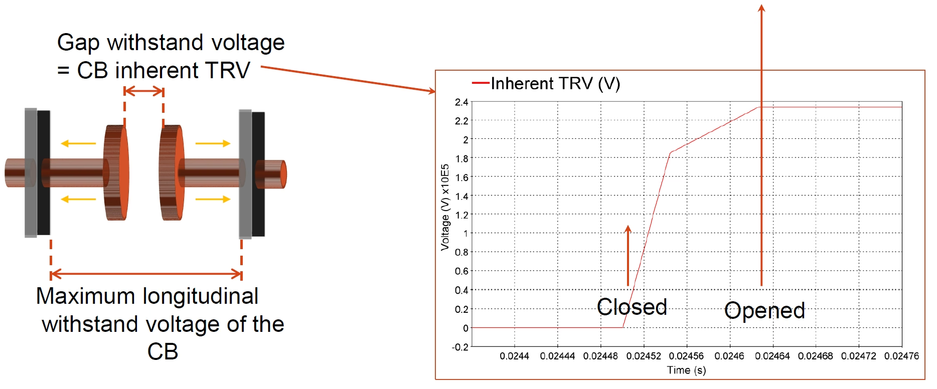
Diagram showing gap withstand voltage equal to CB inherent TRV, with Inherent TRV waveform and contact open/closed markers
Figure 1 — The breaker contacts pull apart. The voltage the gap is able to withstand rises as it opens; the voltage the network would impose on it is the breaker’s inherent TRV. Interruption succeeds while the withstand stays above the inherent TRV.

Figure 1 should be read as a race. The opening contacts create more distance and more insulation strength. At the same time, the network tries to apply a voltage across the gap. The breaker succeeds only while the available gap withstand is higher than the voltage being applied.

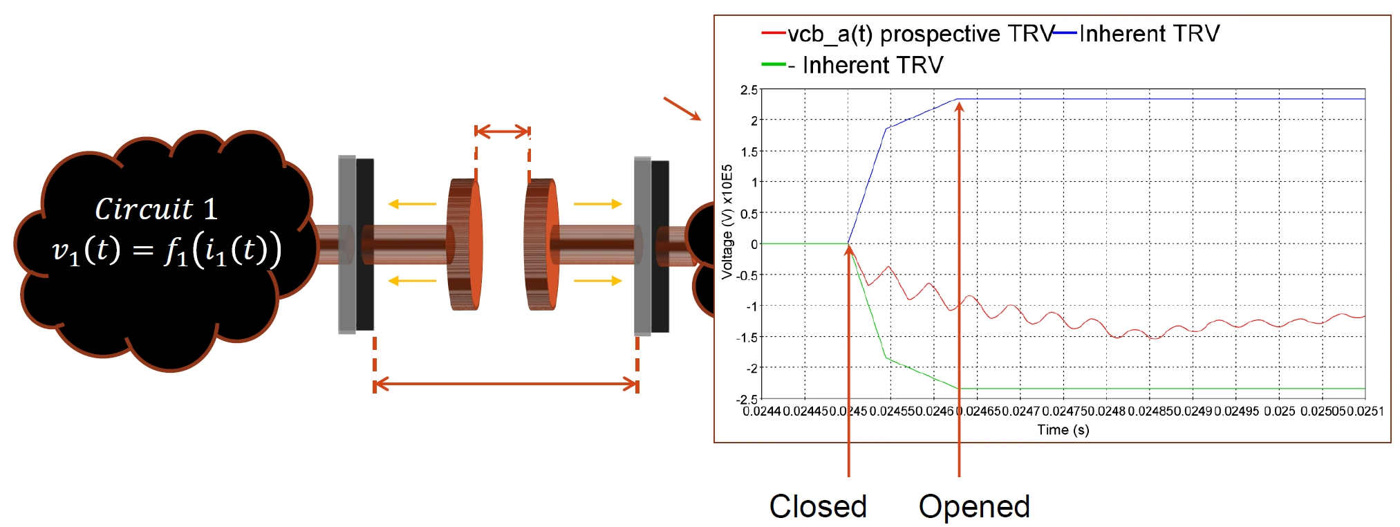
Circuit 1 with contacts separating, showing prospective TRV versus inherent TRV waveform with closed and opened markers
Figure 2 — The same race shown against the voltage waveform. The blue trace is the inherent (prospective) TRV the network would apply; the red trace is the actual voltage that develops. The contacts must be far enough apart by the time the voltage rises.

Figure 2 shows the same idea using the actual voltage waveform. The prospective TRV is the voltage the network would apply to the breaker after an ideal interruption. The actual voltage across the contacts must stay within the breaker capability while the contacts continue to separate.

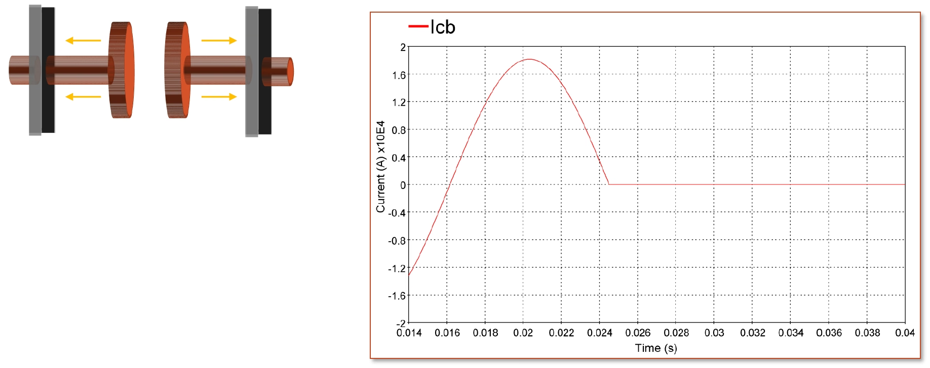
Breaker contacts separating with current waveform showing current going to zero at interruption
Figure 3 — Prospective (inherent) TRV versus the developing voltage, marking the contact-parting and fully-open instants — the breaker must win the race between gap opening and voltage rise.

Figure 3 is important for training because it shows why timing matters. The contacts are not fully open at current zero. They are still moving. Therefore, the first few microseconds after current zero are often the most severe time for the breaker.

Gap failure modes

Reignition and restrike: what these words really mean

Many engineers first meet the words reignition and restrike in standards, test reports or EMT studies. The words sound difficult, but the idea is simple. In both cases the breaker gap breaks down after current interruption. The difference is mainly the time at which it happens.

Reignition

A breakdown of the breaker gap very soon after current interruption, normally within the first quarter-cycle. The arc is re-established before the interruption has properly settled.

Restrike

A breakdown of the breaker gap after a longer time, normally more than a quarter-cycle after interruption. The breaker had appeared to clear, but the gap later failed to withstand the recovery voltage.

In practical discussion, people sometimes use restrike as a general word for both cases. For accurate technical writing, it is better to keep the distinction clear: reignition is early; restrike is later. Both mean that the breaker did not hold the voltage across its open contacts.

Why reignition happens

Reignition usually happens when the contact gap has not recovered fast enough. The gap may still contain hot gas, ionised particles, or metal vapour. The TRV rises across this weak gap. If the electric field becomes too high, the gap conducts again. A new arc path is formed.

In a waveform, reignition is normally seen as a sudden collapse or sharp change in the voltage across the breaker, followed by high-frequency oscillations. The exact shape depends on the network and on the breaker technology.

Why restrike happens

Restrike happens later. It can occur after the gap has already withstood the first part of the recovery voltage. It is often associated with switching capacitive current — capacitor banks, cables, or overhead lines — where the trapped charge and the source voltage create a high voltage across the open contacts.

A restrike is serious because it can create very steep overvoltages in the connected network. In capacitor or cable switching, repeated restrikes can produce voltage escalation, high-frequency transients and insulation stress on nearby equipment — which is why capacitive switching often uses controlled (point-on-wave) switching, covered in the mitigation section.

What happens after current zero in SF6 and vacuum breakers

After current zero there may still be a very small current for a very short time. In SF6 breakers, the gas must remove heat and charged particles from the arc path. In vacuum breakers, the metal vapour from the contacts must condense quickly and the vacuum gap must recover its insulation strength.

Vacuum interrupters can have a small post-arc current immediately after current zero. This does not automatically mean failure. It becomes a problem only if the gap cannot recover and the current grows again into a conducting arc. The engineering question is always the same: does the gap recover faster than the voltage stress returns?

Post-arc current

A small current that may flow immediately after current zero while the gap is recovering. It is different from a successfully re-established arc, but it can indicate how the gap is recovering.

Basic analysis

What voltage is actually across the breaker?

A useful way to understand TRV is to look at the two sides of the breaker. Before the breaker opens, the two terminals are connected through the contacts and arc. Therefore, the voltage across the breaker is small. After interruption, the two sides are separated. The voltage across the breaker is simply the difference between the source-side voltage and the line-side or load-side voltage.

In simple form: voltage across breaker = voltage on side A − voltage on side B.

In a three-phase fault the three poles do not clear together, and the first pole to clear can see a higher voltage than this simple difference suggests — quantified later by the first-pole-to-clear factor kpp (see §8.1).

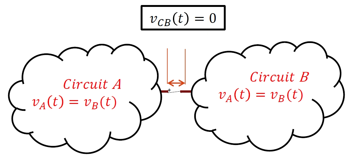
Circuit diagram with breaker closed showing vCB equals zero, Circuit A and Circuit B connected
Figure 4 — Breaker closed — the two circuits are tied together, so the voltage across the breaker is zero.
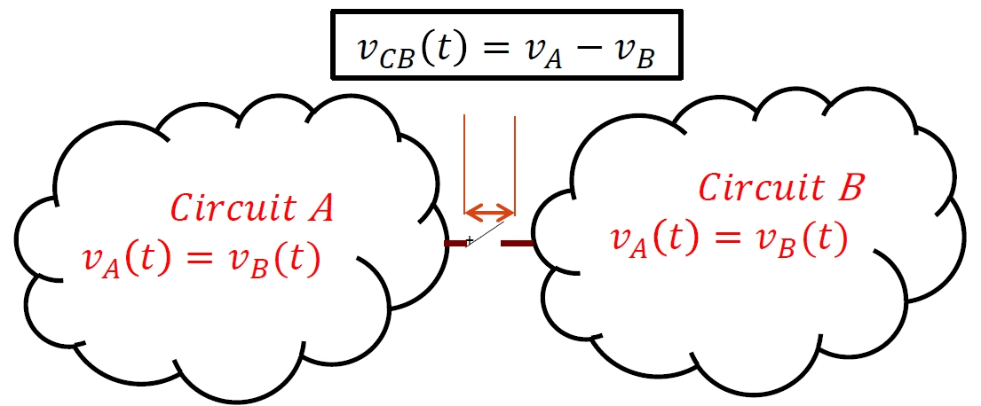
Circuit diagram with breaker open showing vCB equals vA minus vB, Circuit A and Circuit B separated
Figure 5 — Breaker open — the voltage across the contacts becomes the difference between the two sides, vCB = vA − vB.

In Figure 4, the breaker is closed. Both sides are tied together, so the voltage across the breaker is zero or close to zero. In Figure 5, the breaker is open. The two sides can now have different voltages. The difference between those two voltages appears across the breaker contacts. Immediately after interruption, the fast part of that voltage is the TRV.

TRV and recovery voltage are not the same thing

The recovery voltage has two parts.

  • The transient part is the TRV. It is fast and may contain an overshoot or oscillation.
  • The steady part is the power-frequency recovery voltage. It remains after the fast transient has died away.
Recovery voltage

The voltage across the open contacts after interruption. It includes the fast transient part (the TRV) and the later steady power-frequency part.

The first part is normally more dangerous for the breaker because the gap is still recovering. The later steady voltage may be high, but by then the gap should have much more dielectric strength.

Reading the plots

How to read a TRV waveform

A TRV waveform can look complicated, but for breaker duty it is normally reduced to a few important features. The most important are peak voltage, rate of rise, and the time at which the peak occurs.

Peak value: how high the voltage gets

The peak value is the highest point reached by the TRV. Standards often call this uc, meaning the crest value. If the peak is too high, the gap may break down even if the voltage did not rise very fast.

uc — TRV peak

The maximum value reached by the TRV waveform. It is usually given in kV.

What sets that peak? The TRV overshoots the power-frequency recovery voltage, and the size of that overshoot is the amplitude factor, controlled by circuit damping. In a three-phase fault the recovery voltage also depends on which pole clears first. So, conceptually, the peak is the crest of the phase voltage multiplied by the first-pole-to-clear factor and the amplitude factor.

Amplitude factor

The ratio of the TRV peak to the power-frequency recovery-voltage peak — in effect, how far the transient overshoots. A well-damped (overdamped) circuit has a low amplitude factor; an oscillatory (underdamped) circuit has a higher one.

RRRV: how fast the voltage rises

The Rate of Rise of Recovery Voltage is called RRRV. It is the slope of the first part of the TRV curve. It tells us how many kilovolts per microsecond the voltage is applying to the breaker gap.

RRRV — Rate of Rise of Recovery Voltage

The initial slope of the TRV waveform, normally expressed in kV/µs.

Key lesson: RRRV is often the more difficult requirement. A breaker might withstand a high voltage after the gap has recovered, but not a very fast voltage during the first few microseconds. A waveform with a lower peak can still be more severe if it rises faster. Always check RRRV alongside uc.

First line-peak and early TRV stress

In some TRV plots, especially line-related cases, the first important point is called the first line-peak. This is an early peak caused by travelling waves on the line. It matters because it arrives very soon after current zero, when the gap is still weak.

The practical message is simple: do not judge TRV only by the final peak. Always check the first few microseconds. That is where many breaker duties become difficult.

Network behaviour

Why the network creates the TRV shape

The breaker does not create the TRV shape by itself. The network around the breaker creates it. The breaker only initiates the event by interrupting current. After that, the inductance and capacitance of the network exchange energy and create the transient voltage.

Inductance stores energy in a magnetic field. Capacitance stores energy in an electric field. When current is interrupted, the energy cannot disappear instantly. It moves between inductance and capacitance. This movement produces the oscillation or rise of the TRV.

Stray capacitance

Small capacitance that naturally exists between conductors and earth, between windings and tanks, across bushings, along cables, and inside switchgear. It strongly influences TRV because TRV events unfold on a microsecond timescale where even small capacitances matter.

This is why two breakers with the same rating can see different TRV stresses at different locations. A breaker connected to a cable system may see a slower TRV because the cable capacitance is large. A breaker connected to an overhead line may see a faster TRV because the capacitance is lower and travelling waves become important.

Three common TRV shapes

Overdamped

Smooth rising TRV

Rises smoothly toward the final recovery voltage with little overshoot. Usually means the circuit has enough damping. Normally easier for the breaker than a very steep or highly oscillatory waveform.

Underdamped

Oscillatory TRV

Overshoots and rings before settling. Common when the circuit has inductance and capacitance but not much damping. Transformer-fed or reactor-related duties often produce this kind of waveform.

Short-line fault

Steep ramp TRV

A fault on an overhead line close to the breaker. The small length of line behaves like a travelling-wave section. The TRV can rise as a steep ramp or sawtooth. Difficult even when the peak is not the highest — the problem is the speed of the rise.

Surge impedance

The ratio of voltage to current for a travelling wave on a line — a property of the line geometry. It directly controls the slope of short-line-fault TRV. Higher surge impedance means a steeper initial rise.

Switching duties that also create TRV

TRV is not only a fault-interruption problem. Two switching duties are worth singling out:

  • Transformer-limited fault. The transformer leakage reactance limits the current while the terminal capacitance is small. This can give a steep TRV and a high RRRV even though the current is not the maximum short-circuit value.
  • Shunt-reactor switching and current chopping. When a breaker chops a small inductive current just before its natural zero, the trapped magnetic energy transfers to the local capacitance and can drive a fast recovery voltage and overvoltage.

The calculation concepts behind these cases are developed in the TRV Calculation Concepts companion.

Standards & testing

Breaker capability: the TRV envelope

A breaker manufacturer proves the breaker capability by testing. The tested capability is shown as a TRV envelope — a boundary curve on a voltage-time plot. The application rule is visual and direct: the network TRV must stay below the breaker envelope for the whole time range. If any part of the network TRV is above the envelope, the breaker is not guaranteed for that duty.

Rated TRV envelope

The voltage-time boundary that represents the TRV a breaker has been tested to withstand. The calculated network TRV must remain below it.

Standards: the TRV duties, envelopes and classes described here follow IEC 62271-100 for AC circuit breakers, with equivalent treatment in the IEEE C37 series (C37.04, C37.06 and C37.011 for TRV application).

Two-parameter envelope

A two-parameter envelope is used where the TRV can be represented by one main rise to a peak. The two key values are the peak voltage uc and the time to peak t3, and the initial slope — the RRRV — is approximately RRRV ≈ uc / t3.

Two-parameter TRV

A simple TRV withstand envelope defined mainly by a peak value uc and a time to peak t3.

Four-parameter envelope

A four-parameter envelope is used when the first part of the TRV rises quickly and the later part rises more slowly. It uses an early point to represent the fast initial slope and a later point to represent the peak.

Four-parameter TRV

A TRV withstand envelope defined by four values: an early reference voltage u1 and time t1 (which fix the fast initial slope), plus the peak uc and time t3. It is used where the initial rate of rise is an important separate check from the peak voltage.

Test duties T10, T30, T60 and T100

A breaker is tested at several percentages of rated short-circuit current. This is necessary because the TRV does not always become easier when the current is lower. In many cases, lower current duties can have faster RRRV.

Table 1 — Standard short-circuit test duties and their relative TRV severity.
Test DutyMeaning for Training
T100Interruption of 100% of rated short-circuit current. The current is highest, but the TRV rate of rise is often not the most severe.
T60Interruption of 60% of rated short-circuit current. An intermediate duty.
T30Interruption of 30% of rated short-circuit current. The TRV can have a faster initial rise and may require a four-parameter check.
T10Interruption of 10% of rated short-circuit current. This can be severe for RRRV even though the current is relatively low.
Key lesson: Do not check only the maximum fault current. A smaller fault current can still be a difficult TRV duty if the voltage rises very quickly.

Breaker classes S1 and S2

For some voltage ranges, breakers are classified according to the network type. Cable networks and overhead-line networks do not produce the same TRV stress.

Table 2 — Breaker classes S1 and S2 compared for cable and overhead-line systems.
ClassDesigned forTRV StressTypical Application
S1Cable-connected systemsLower rate of rise and generally easier TRVIndustrial and urban distribution networks
S2Overhead-line systemsHigher rate of rise and more severe TRVRural feeders and overhead-line applications

A breaker suitable for a cable-fed network should not automatically be assumed suitable for an overhead-line feeder. The overhead line may impose a much steeper TRV.

Useful related terms

ITRV — Initial Transient Recovery Voltage

A very fast initial spike caused by the local busbar, short connections and nearby equipment capacitances and inductances close to the breaker. In IEC-style application work, it is generally considered for higher-voltage circuit breakers, commonly above about 100 kV, where local substation geometry and surge impedance can control the first microseconds.

Out-of-phase switching

Opening a breaker when the two sides of the system are not in synchronism. The recovery voltage can be much higher than normal and must be checked separately from normal fault duties.

Per-unit

A way of expressing a voltage as a multiple of a base voltage. For example, 1.5 p.u. means 1.5 times the base voltage.

Engineering practice

Practical TRV study workflow

A TRV study should answer one practical question: can this breaker interrupt this fault or switching duty at this location in this network? A good workflow is simple and structured.

Start with the duty and the breaker data

  • Identify the breaker voltage rating, current rating, interruption rating, TRV class and TRV envelope.
  • Identify the fault or switching duty: terminal fault, line fault, short-line fault, reactor switching, capacitor switching, transformer-limited fault, or out-of-phase switching.
  • Identify the system earthing and the first-pole-to-clear condition if it is relevant.

The first pole to clear can see a higher recovery voltage than the other poles in a three-phase fault, depending on the network earthing and fault condition. This is represented by the first-pole-to-clear factor, kpp, which is typically about 1.3 for effectively earthed systems and about 1.5 for non-effectively earthed systems. This is why TRV studies must consider the correct pole and not only the average three-phase behaviour.

Do a first engineering check

For a first check, the network can often be reduced to an equivalent inductance, capacitance and damping resistance. This does not replace a detailed study, but it helps the engineer understand the expected shape and severity of the TRV.

  • A larger capacitance usually slows the initial voltage rise.
  • A larger inductance can increase oscillation and can change the TRV frequency.
  • More damping reduces overshoot and ringing.
  • Overhead-line travelling waves can create a steep short-line-fault TRV.

Use realistic capacitance values

Small capacitances become important because TRV happens on a microsecond timescale. The capacitance close to the breaker should therefore be represented with care.

Table 3 — Typical stray capacitance values for substation equipment near the breaker.
EquipmentTypical Stray Capacitance
High-voltage bushings1,000 – 3,000 pF
Dead-tank circuit breaker300 – 1,500 pF per phase
Gas-insulated switchgear (GIS)25 – 50 pF per metre
Cable50 – 100 pF per metre
Current transformer (CT)100 – 200 pF
Voltage transformer (VT)200 – 500 pF
Transformer winding to ground5 – 50 nF
These values are typical only. Manufacturer data and project-specific layout data should be used where available. For sensitive cases, the study result can change noticeably when local capacitances are changed.

Use EMT simulation for complex networks

For complex cases, hand calculations are not enough. EMT simulation is used because it calculates the waveform step by step in time. This is the correct approach for detailed TRV studies involving lines, cables, GIS, transformers, reactors, capacitor banks, surge arresters and realistic switching instants.

EMT study — Electromagnetic Transients study

A time-domain simulation used to calculate fast events such as TRV, switching surges and travelling waves.

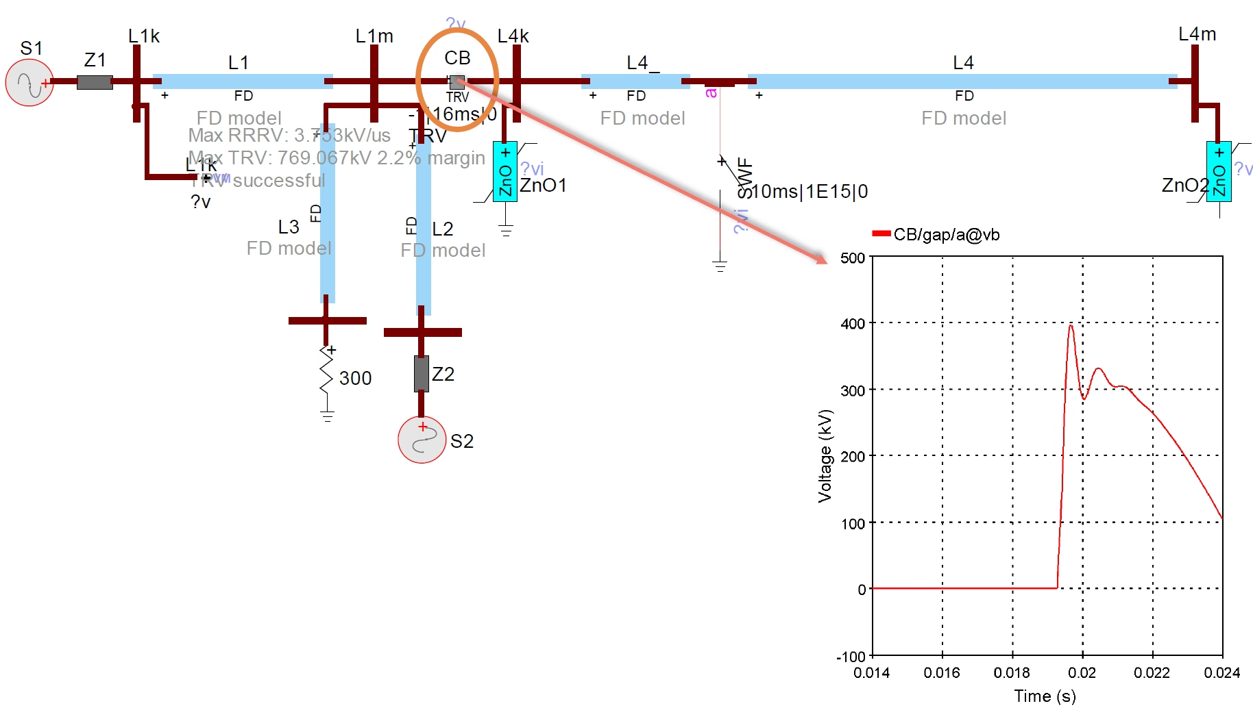
EMT study network diagram showing breaker with maximum RRRV and TRV results reported against the breaker rating
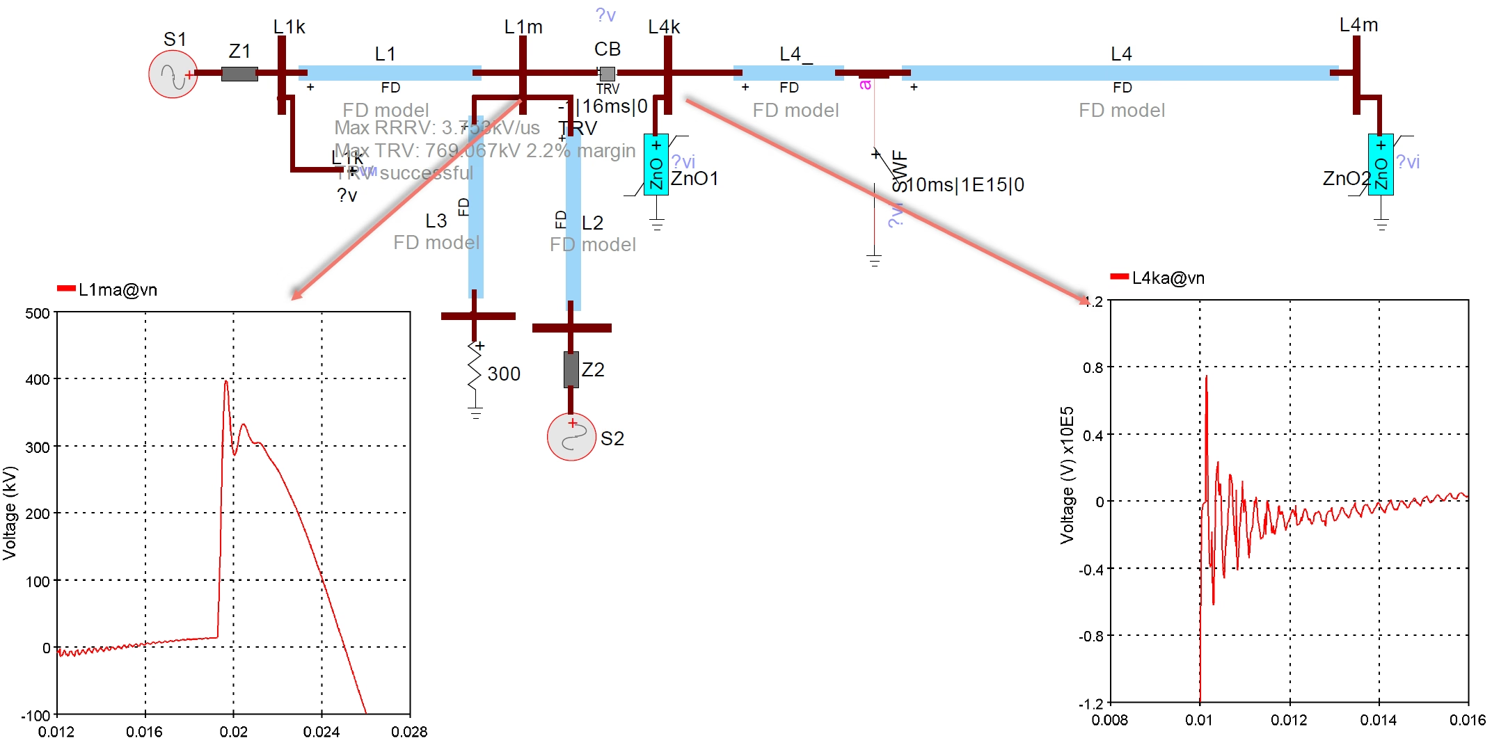
Figure 6 — An EMT (EMTP®) study of a transmission network. The breaker CB reports its results directly: maximum RRRV and maximum TRV, with the margin against the breaker rating. The left plot is the TRV at the breaker; the right plot is the fast oscillation seen on the line side.

Figure 6 shows an example EMT model. The software calculates the voltage across the breaker and can report the maximum TRV and RRRV. The engineer then compares these values and the full waveform against the breaker rating.

Simulated TRV waveform from EMT study showing voltage peak and decay compared to the breaker rated envelope
Figure 7 — The TRV waveform across the breaker from the same study. This is the real, simulated shape that must stay under the breaker’s rated envelope. In this zoomed view the visible local peak is near 400 kV; the study readout in Figure 6 reports the overall maximum TRV for the selected monitored quantity.

Figure 7 shows the simulated TRV waveform across the breaker. In a proper study, the waveform is not checked only by its maximum point or by one plotted time window. It is compared against the whole rated TRV envelope, and the reported maximum TRV and RRRV values from the study must also be reviewed.

When TRV is too severe

What to do if the TRV is too severe

If the calculated TRV is above the breaker envelope, the application is not acceptable as it stands. The engineer then has two choices: reduce the TRV stress or use a breaker with higher capability.

Mitigation options
  1. Use a breaker with a higher TRV rating. Often the cleanest technical solution, especially if the issue is short-line-fault duty or a high RRRV requirement.
  2. Add TRV capacitors. A capacitor connected across the breaker, transformer or reactor can slow the voltage rise and reduce RRRV.
  3. Add damping. A damping resistor, often used with capacitance, can reduce oscillation and overshoot. The resistor and capacitor must be sized together.
  4. Change the network arrangement. Sometimes a different switching sequence, busbar arrangement, cable length or line connection can reduce the stress.
  5. Use controlled switching where applicable. Point-on-wave switching can reduce some switching transients, especially for capacitor banks, reactors and transformers. It is not a substitute for breaker rating, but it can be a useful mitigation.
  6. Review fault-current limitation carefully. Reducing fault current can reduce some stresses, but it can also move the duty into a faster RRRV range. The TRV must be checked again after any network change.
Controlled switching: Opening or closing a breaker at a selected point on the voltage or current waveform to reduce the resulting transient.

Learning checklist

Common mistakes when learning TRV

  • Looking only at the TRV peak and ignoring RRRV.
  • Assuming the maximum fault current is always the worst TRV case.
  • Forgetting that the first few microseconds after current zero are the most critical period.
  • Assuming a cable application and an overhead-line application have the same TRV duty.
  • Using unrealistic or missing capacitance values near the breaker.
  • Confusing recovery voltage, transient recovery voltage, reignition and restrike.
  • Comparing only one point of the TRV waveform instead of comparing the complete waveform with the breaker envelope.

Key concept

Putting the idea together

A circuit breaker clears an AC fault by extinguishing the arc at current zero. At that same moment, the network applies a fast recovery voltage across the opening contacts. This voltage is the TRV.

The breaker succeeds if its contact gap recovers insulation strength faster than the TRV rises. It fails if the gap breaks down again. If the breakdown happens very soon, it is called reignition. If it happens later, it is called restrike.

The shape of the TRV comes mainly from the network, not from the breaker. Inductance, capacitance, damping, lines, cables, transformers and reactors all influence the waveform. The breaker capability is expressed as a rated TRV envelope. The engineer checks that the network TRV stays below this envelope for the relevant duties.

TRV is the voltage race immediately after current zero, and the breaker must win that race.

Reference

Quick glossary

Table 4 — Plain-language glossary of the key TRV and switching terms.
TermPlain-Language Meaning
ArcHot conducting path between breaker contacts while they are separating.
Current zeroThe instant when AC current passes through zero and interruption is possible.
Dielectric strengthThe voltage an insulation gap can withstand before breakdown.
TRVFast transient voltage across the breaker contacts immediately after interruption.
Recovery voltageThe voltage across the open contacts after interruption — includes the transient part and the later steady power-frequency part.
RRRVRate of Rise of Recovery Voltage; the initial slope of the TRV waveform in kV/µs.
ucThe peak or crest value of the TRV.
ReignitionEarly breakdown of the breaker gap soon after current interruption (within the first quarter-cycle).
RestrikeLater breakdown of the breaker gap after it had appeared to clear (more than a quarter-cycle after interruption).
Post-arc currentSmall current immediately after current zero while the gap is recovering.
Overdamped TRVSmooth TRV with little or no oscillation — circuit has enough damping.
Underdamped TRVOscillatory TRV with overshoot and ringing — low-damping circuit.
Short-line faultFault on an overhead line close to the breaker, often producing high RRRV.
Surge impedanceLine property controlling the voltage-to-current ratio of a travelling wave — directly sets short-line-fault TRV slope.
Rated TRV envelopeBreaker withstand boundary on a voltage-time plot. The calculated network TRV must stay below it.
ITRVInitial Transient Recovery Voltage — very fast local spike near the start of TRV, generally relevant for higher-voltage breakers and local busbar/connection effects.
EMT studyElectromagnetic Transients study — time-domain simulation used to calculate TRV, switching surges and travelling waves.
Controlled switchingSwitching at a selected point on the waveform to reduce the resulting transient.
First-pole-to-clear factor (kpp)Factor for the higher recovery voltage on the first pole to clear in a three-phase fault — about 1.3 (effectively earthed) or 1.5 (non-effectively earthed).
Amplitude factorRatio of the TRV peak to the power-frequency recovery-voltage peak; how far the transient overshoots, set by damping.
Two-/four-parameter TRVEnvelope shapes: two-parameter uses a peak uc and time t3; four-parameter adds an early point (u1, t1) for the fast initial slope.
T10 / T30 / T60 / T100Standard test duties at 10 / 30 / 60 / 100 % of rated short-circuit current; lower-current duties can have a faster RRRV.
S1 / S2Breaker classes for cable-fed (S1) and overhead-line (S2) systems; S2 imposes a more severe TRV.
Out-of-phase switchingOpening when the two sides are not in synchronism; the recovery voltage can be much higher than normal.

Two-Part Technical Series

Transient Recovery Voltage

A two-part guide to transient recovery voltage — Part One explains what TRV is and how to read it (the interruption race at current zero, reignition and restrike, waveforms, the breaker envelope and mitigation); Part Two develops the calculation concepts (current injection, inductive interruption and stray capacitance, transformer-limited and short-line faults, line surge impedance and the first pole to clear).

Part One Reading now

Understanding TRV — the Training Guide

What TRV means, the interruption race at current zero, reignition and restrike, reading TRV waveforms, the breaker capability envelope and standards, the study workflow and mitigation options.

Series progress 1 of 2