Inductive Switching

Shunt Reactor Switching

How AC high-voltage circuit breakers are applied to shunt reactor switching — current chopping, reignition and voltage escalation, the effect of grounding on the recovery voltage, and how surge arresters, opening resistors and controlled opening hold the stress to acceptable values. Based mainly on IEEE Std C37.015.

Reading time ≈ 25 min

Section 1

What a Shunt Reactor Does, and Why Switching It Is Awkward

This page complements the capacitive-switching notes by covering the opposite type of duty: switching a mainly inductive load, where the current is usually small but the recovery voltage and reignition risk can be severe.

A shunt reactor is an inductive load used to absorb reactive power and help hold voltage down, particularly on long lines or cables under light load. Reactors are switched often — sometimes daily — to follow changes in system loading, so the breaker also needs good mechanical endurance.

The reactor current is usually relatively small compared with fault current, commonly of the order of a few hundred amperes, so the challenge is normally not thermal interruption capability but dielectric recovery and overvoltage control. The difficulty is that the breaker may force the small inductive current to zero before its natural zero — current chopping — trapping energy in the reactor and producing an overvoltage across the open contacts. Two effects dominate: current chopping and reignition.

The duty is therefore voltage-dominated rather than current-dominated: the breaker can usually interrupt the current, but it must then withstand the recovery voltage without reignition.
About the per-unit values here

The guidance follows IEEE Std C37.015 (the active 2017 revision, which superseded the 2009 edition). The per-unit and overvoltage values quoted here are taken from the guide’s own worked example and are conditional on its assumptions. They are useful for understanding severity, but should not be treated as fixed project limits without checking the actual circuit.

Section 2

Current Chopping

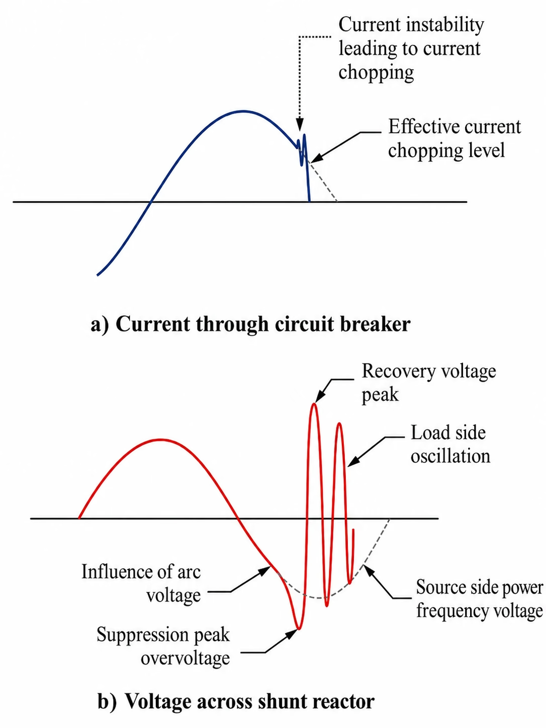
A breaker does not always wait for the natural current zero. With a small inductive current, arc instability forces the current prematurely to zero — this is called current chopping, and it can be treated as effectively instantaneous. The magnetic energy left in the reactor must then transfer into the load-side capacitance, producing an oscillatory overvoltage. The chopped current is set by the breaker’s chopping number and the capacitance in parallel with it; it is largely a property of the breaker and its interrupting medium. SF6 self-blast and rotating-arc designs chop very little; air-blast and minimum-oil designs chop more.

For a single-interrupter breaker the chopped current follows from the chopping number \(\lambda\) and the capacitance in parallel with the interrupter; for \(N\) interrupting units per pole that capacitance scales with \(N\):

\[ i_{ch} = \lambda\sqrt{C_{t}} \qquad i_{ch} = \lambda\sqrt{N\,C_{t}}\ \text{(N units per pole)} \qquad C_{t} = C_{p} + \dfrac{C_{s}\,C_{L}}{C_{s}+C_{L}} \]
\(i_{ch}\)
chopped current level (A)
\(\lambda\)
chopping number of the interrupter (A·F−0.5), found by laboratory test
\(C_{t}\)
total capacitance in parallel with the breaker (F); with \(C_{s}\gg C_{L}\) it reduces to \(C_{p}+C_{L}\)
\(C_{p},C_{s},C_{L}\)
breaker parallel, source-side and load-side capacitances (F)
\(N\)
interrupting units in series per pole

The chopping number characterises how strongly a breaker technology tends to chop small inductive currents. It is a property of the interrupter and applies to every type except vacuum, where the degree of chopping is set mainly by the contact material. Typical ranges span nearly two orders of magnitude:

Table 1 — Typical circuit-breaker chopping numbers.
Circuit-Breaker TypeChopping Number \(\lambda\) (A·F−0.5)
Minimum oil5.8×104 to 10×104
Air blast15×104 to 20×104
SF6 puffer4×104 to 19×104
SF6 self-blast3×104 to 10×104
SF6 rotating arc0.39×104 to 0.77×10⁴
Easy to get wrong: chopped current ≠ load current

The chopped current is not simply equal to the reactor load current. It is a statistical, interrupter-dependent value influenced by the interrupter design and the local capacitance. If a reactor draws 200 A, the chopped current is not 200 A — it is the much smaller instantaneous current forced to zero just before the natural current zero, and its magnitude depends strongly on breaker technology.

After chopping, the reactor current stops abruptly. The reactor inductance and the load-side capacitance then exchange energy, typically at about 1 to 5 kHz: the first peak of that oscillation is the suppression peak overvoltage, and the following opposite-polarity peak contributes to the recovery voltage across the open breaker contacts. For a directly grounded reactor the recovery voltage peak is no greater than the suppression peak.

The size of the suppression peak follows from the chopped current and the reactor loop. In per unit of \(V_{o}\) (the crest voltage across the reactor at interruption) it is:

\[ k_{a} = \dfrac{V_{ma}}{V_{o}} = \sqrt{1 + \dfrac{i_{ch}^{2}}{V_{o}^{2}}\cdot\dfrac{L}{C_{L}}} \;\approx\; \sqrt{1 + \dfrac{3N\lambda^{2}}{2\omega Q}} \]
\(k_{a}\)
suppression peak overvoltage (pu of \(V_{o}\)); the recovery-voltage peak \(k_{c}\approx k_{a}\) for a grounded reactor
\(V_{ma}\)
suppression-peak voltage to ground (V)
\(L,C_{L}\)
reactor inductance (H) and load-side capacitance to ground (F)
\(Q\)
three-phase reactor rating (VA)
\(\omega\)
angular power-system frequency, \(2\pi f\)

The right-hand form (valid when \(C_{s}\gg C_{L}\) and \(C_{p}\) is negligible) makes the key point: the chopping overvoltage depends only on the chopping number and the reactor rating — a smaller, lower-rated reactor switched by a high-chopping breaker gives the highest overvoltage. Because the load-side oscillation is only lightly damped, the opposite-polarity recovery-voltage peak is of nearly the same magnitude.

Current chopping: (a) the breaker current, where arc instability forces the current to zero at the effective chopping level ahead of the natural zero; (b) the resulting voltage across the shunt reactor, showing the suppression peak overvoltage, the recovery voltage peak, the load-side oscillation and the source-side power-frequency voltage.
Figure 1 — Current chopping phenomena: (a) current through the circuit breaker and (b) the resulting voltage across the shunt reactor (after IEEE C37.015).

Section 3

Reignition

After the current is chopped, the voltage across the open contacts is the difference between the source-side voltage (near its crest) and the oscillating load-side voltage. If the contacts have not yet separated far enough to withstand that voltage, the gap breaks down again — a reignition.

Practical interpretation

Every breaker will reignite if it interrupts with too small a contact gap. Reignition is not magic, and it is not only a “bad breaker” problem. It is a race between two quantities: the recovery voltage building up across the contacts, and the dielectric strength recovering across the widening contact gap. If the voltage rises faster than the gap strength recovers, the gap breaks down again.

Whether a reignition happens depends on the contact-parting instant relative to current zero and on how fast the gap regains strength (its rate of rise of dielectric strength). Reignitions create steep, fast transients — fronts from under a microsecond to a few microseconds. Because the front is so steep, the voltage does not distribute evenly along the reactor winding, so the entrance turns can see higher stress than the power-frequency voltage would suggest, and winding resonances can be excited.

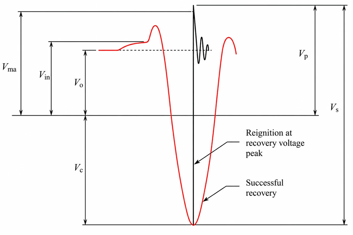
A reignition drives the load-side voltage past the source voltage and overshoots. With damping, the reignition overvoltage peak to ground \(k_{p}\) and its peak-to-peak excursion \(k_{s}\) (both in per unit of \(V_{o}\)) are:

\[ k_{p} = 1 + \beta\,(1 + k_{a}) \qquad\qquad k_{s} = (1 + \beta)\,(1 + k_{a}) \]
\(k_{p}\)
reignition overvoltage peak to ground (pu of \(V_{o}\))
\(k_{s}\)
reignition overvoltage excursion, peak-to-peak (pu of \(V_{o}\))
\(\beta\)
damping factor, normally not exceeding 0.5
\(k_{a}\)
suppression peak at the current zero where the reignition occurs

These are the directly grounded forms. An ungrounded reactor, or one grounded through a neutral reactor, raises the bracketed term (to \(2+k_{a}\) and \(1+2K+k_{a}\) respectively), which is why the grounding arrangement governs the severity (Section 5).

Voltage across the shunt reactor during chopping and reignition, marking the reference voltage Vo, the with-arc-voltage level Vin, the suppression peak Vma, the recovery voltage peak Vc, the reignition overvoltage peak Vp and the peak-to-peak excursion Vs, with a reignition occurring at the recovery-voltage peak and, alternatively, a successful recovery.
Figure 2 — Chopping and reignition overvoltage phenomena, showing the voltages that define the per-unit factors \(k_a\), \(k_c\), \(k_p\) and \(k_s\) (after IEEE C37.015).

The figure marks the switching voltages directly; dividing each by the reference voltage \(V_o\) gives the per-unit factor used above:

\(V_o\)
voltage across the reactor at current interruption, arc voltage not significant — the reference, taken as 1 pu
\(V_{in}\)
voltage across the reactor at interruption when arc voltage is significant (an effect that matters mainly below 60 kV); \(k_{in}=V_{in}/V_o\)
\(V_{ma}\)
suppression peak overvoltage to ground; \(k_a=V_{ma}/V_o\)
\(V_c\)
recovery voltage peak to ground; \(k_c=V_c/V_o\)
\(V_p\)
reignition overvoltage peak to ground; \(k_p=V_p/V_o\)
\(V_s\)
reignition overvoltage excursion, peak-to-peak; \(k_s=V_s/V_o\)

A reignition is not a single-frequency event. After a clean interruption the load side rings slowly as trapped energy swaps between \(L\) and \(C_L\):

\[ f_{L} = \dfrac{1}{2\pi\sqrt{L\,C_{L}}} \]
\(f_{L}\)
load-side oscillation frequency (Hz) — 1–5 kHz for oil-filled reactors, two to three times higher for dry-coil units
\(L,C_{L}\)
reactor inductance (H) and load-side capacitance (F)

When a reignition does occur, the transient unfolds as a sequence of much faster oscillations, as different parts of the circuit discharge and re-share their charge at different frequencies. An EMT study has to capture the whole span — from the low-frequency reactor oscillation to the very fast breaker and capacitance transients, a few kilohertz to several megahertz — so the four modes below set the bandwidth and time-step the model needs.

Table 2 — Oscillation modes during interruption and reignition (after IEEE C37.015 Annex D).
ModeFrequency RangeWhat Is Oscillating
Load side1–5 kHzTrapped energy ringing between the reactor and its load-side capacitance after a successful interruption.
First parallel1–10 MHzThe breaker’s own parallel capacitance discharging through the arc at reignition; the breaker cannot interrupt this current.
Second parallel50 kHz–1 MHzSource- and load-side capacitances equalising — the reignition overvoltage oscillation; the breaker may or may not interrupt it.
Main circuit2–20 kHzThe whole circuit ringing if the second-parallel current is not interrupted; absent when the source-side capacitance greatly exceeds the load-side.

This sequence is what links reignition to escalation (next section): if the breaker interrupts one of these fast currents, the load side is left charged and the next reignition can be larger. A further effect — beating of the recovery-voltage oscillation from phase-to-phase coupling, seen with longer breaker-to-reactor connections and three-phase (single-tank) reactors — does not change the first recovery-voltage peak, so it does not alter the reignition risk and is not a design concern here.

Section 4

Voltage Escalation

If a reignition is followed by a fresh interruption during the high-frequency oscillations, the load-side oscillation restarts. Each interruption can leave the reactor side charged to a more severe voltage, so the next reignition starts from a worse initial condition and can be larger than the last. Repeated, this is voltage escalation.

It is most associated with vacuum breakers, mainly because vacuum interrupters can interrupt high-frequency currents — allowing the load-side voltage to be trapped again at a more severe value. More generally, it becomes relevant where the high-frequency current is within the interrupting capability of the interrupter; reignition transient frequencies below roughly 100 kHz are often cited as a range where the risk becomes more relevant, though this should be read as a guide rather than a hard boundary.

Section 5

The Three Grounding Cases

The grounding arrangement controls how much the reactor neutral can shift after the first pole clears, and that neutral shift changes both the voltage to ground on the reactor side and the recovery voltage across the breaker contacts. The standard treats three arrangements: the directly grounded case is the reference, and the other two are described as deviations from it. As a rule, the more the neutral is allowed to shift, the more severe the recovery-voltage duty becomes. The per-unit figures below are conditional on the assumptions in the guide’s worked example (in which the suppression peak overvoltage \(k_a\) is around 1.3 pu); they show the relative severity of the three arrangements rather than universal results, and the duty for a real installation should be calculated from the project circuit parameters.

\[ V_{rv}\approx(1+k_a)\ \text{pu (grounded)} \qquad V_{rv}\approx(2+k_a)\ \text{pu (ungrounded)} \qquad V_{rv}\approx(1+k_a+2K)\ \text{pu (neutral reactor)} \]
\(V_{rv}\)
recovery-voltage peak across the breaker
\(k_a\)
suppression peak overvoltage (≈ 1.3 pu in the worked example)
\(K\)
factor depending on the ratio of main to neutral inductance
Table 3 — Effect of grounding on recovery voltage and switching duty (worked-example assumptions).
ArrangementRecovery-Voltage PeakComment
Directly grounded (60 kV and above)≈ 2.3 pu  \((1+k_a)\)The simplest, reference case. Energising transient on switching in stays at 1.5 pu or less.
Ungrounded (typically below 60 kV, transformer tertiaries)≈ \((2+k_a)\) puCurrent is several times to an order of magnitude higher, approaching the breaker’s continuous rating — duty resembles a low-current terminal fault. Surge arresters strongly advised.
Grounded through a neutral reactor≈ 2.9 pu  \((1+k_a+2K)\)Used to allow single-pole reclosing; behaves as a blend of the other two. Usually bypassed with a disconnect before opening to bring the duty closer to the directly grounded case.

For the ungrounded case, surge arresters to protect the reactor and the transformer tertiary are strongly advised. For the neutral-reactor case, if the neutral reactor remains in service during switching the recovery-voltage duty can be more severe and may not be represented by the standard test condition for a directly grounded reactor. Bypassing it before opening reduces the neutral shift and brings the switching duty closer to the directly grounded case, which is usually less severe and better represented by standard test conditions.

Section 6

Recovery Voltage Matters More Than the Current

For shunt reactor switching the breaker is not selected mainly by the reactor current — that is easy to interrupt. It is selected by whether it can withstand the recovery voltage across the contacts without reignition.

How high both quantities go is set by a single parameter — the neutral-shift factor \(K\), the per-unit bias the reactor neutral takes up after the first pole clears: \(K=0\) directly grounded, \(0.5\) ungrounded, and an intermediate value fixed by the neutral-to-main inductance ratio for a neutral reactor. A larger \(K\) means a larger neutral shift, and therefore a larger voltage across the remaining open contacts. Writing the recovery peak to ground as \(k_c\) and the recovery voltage across the open contacts as \(k_{rv}\):

\[ k_{c} = K + \alpha\,(k_{a} + K) \qquad\qquad k_{rv} = 1 + K + \alpha\,(k_{a} + K) \]
\(k_{c}\)
overvoltage peak to ground at recovery (pu of \(V_o\)) — what the reactor surge arrester must handle
\(k_{rv}\)
recovery-voltage peak across the open contacts (pu of \(V_o\)) — what drives reignition; note \(k_{rv}=k_c+1\)
\(K\)
neutral-shift factor: 0 grounded, 0.5 ungrounded, intermediate for a neutral reactor
\(\alpha\)
chopping-oscillation damping; \(\alpha=1\) is the conservative value, \(\alpha\le0.9\) is more realistic

With \(\alpha=1\) this gives \(k_{rv}=1+k_a\) grounded, \(k_a+2\) ungrounded, and \(1+k_a+2K\) for the neutral-reactor case — the across-the-breaker figures used in Section 5. It also shows why the ungrounded and neutral arrangements are the more onerous: the neutral shift \(K\) adds directly to both the ground-referenced stress on the arrester and the across-contact stress that governs reignition.

Symbol note. On this page \(k_a\), \(k_c\) and \(k_{rv}\) denote the reactor-switching suppression peak, recovery-to-ground and across-contact overvoltages. Do not confuse \(k_c\) here with the capacitive-switching voltage factor \(k_c\) used on the capacitor-switching pages.

Suppression peak overvoltage limit (2% statistical value)

The standard recommends specifying a suppression peak overvoltage limit of 2 pu for 60 kV and above, and 2.5 pu below 60 kV. This is a value the user can specify as part of the breaker duty.

Reignition overvoltages, by contrast, depend strongly on the user’s own circuit and should normally be assessed by system calculation or EMT simulation rather than specified as a generic breaker rating.

Section 7

Limiting the Overvoltages

The overvoltages cannot be eliminated, but they can be held to acceptable values by the following means. These do not all act in the same way: surge arresters limit the reactor terminal voltage to ground, metal-oxide varistors across the breaker limit the contact-gap voltage, opening resistors soften the interruption, and controlled opening lowers the probability of reignition by improving the contact-parting instant.

Voltage clip

Reactor surge arresters

Metal-oxide arresters clip the load-side voltage at their protective level, reducing the chance of reignition by lowering the recovery-voltage peak, and limiting peak-to-peak reignition excursions to about twice the protective level. They absorb little energy and do not stop chopping — only limit its voltage. Effectiveness depends on arrester location and connection-lead inductance, especially for steep fronts.

Soft interruption

Opening resistors

A resistor (of the order of the reactor’s ohmic reactance, often several thousand ohms) is switched across the main interrupter. The main contacts still chop, but the current commutates to the resistor and final interruption happens in the resistor switch — a softer interruption with low chopping and reduced reignition risk.

Across breaker

Metal-oxide varistors

Applied like a grading capacitor, a varistor across the breaker limits the voltage to its protective level, capping both chopping and reignition overvoltages.

Most effective

Controlled opening

The most effective way to eliminate reignitions in modern breakers — described in its own section below.

Two of these give a firm quantitative ceiling, because each holds a voltage to its own protective level \(k_{var}\) (in per unit of \(V_o\)). A varistor across the breaker — connected like a grading capacitor — holds the contact-gap voltage to \(k_{var}\), which caps the chopping and reignition overvoltages of Sections 2 and 3:

\[ k_{a} \le 1 + k_{var} \qquad k_{p} \le 1 + \beta\,k_{var} \qquad k_{s} = (1 + \beta)\,k_{var} \]
\(k_{var}\)
varistor protective level (pu of \(V_o\)) — the level to which its operation holds the voltage across the breaker
\(k_{a}\)
capped suppression peak overvoltage (pu of \(V_o\))
\(k_{p},k_{s}\)
capped reignition overvoltage peak and peak-to-peak excursion (pu of \(V_o\))
\(\beta\)
damping factor, normally not exceeding 0.5

Choosing \(k_{var}\) therefore sets the switching-overvoltage ceiling directly. The difference between the two devices is where they act: a reactor-side arrester limits the voltage to ground at the reactor terminal, whereas a varistor across the breaker limits the voltage directly across the open contacts. Both conduct only on the fraction of the oscillation that exceeds their characteristic, so the energy they absorb is a small part of that stored in the reactor.

Historical note — gapped surge arresters

Older installations used nonlinear-resistor arresters with series spark gaps rather than the gapless metal-oxide units standard today. A gapped arrester does nothing until the voltage reaches its sparkover level; once it flashes over it discharges the trapped load-side energy and can drive the load-side voltage briefly to near zero. Its protection is therefore set by the sparkover characteristic rather than a continuous clipping curve, so both lightning-impulse (1.2/50 µs) and switching-surge sparkover have to be considered. They paired naturally with high-chopping breakers such as air-blast types, where the suppression peak was large enough to spark them over; with a low-chopping breaker (an SF6 puffer, say) the chopping peak may stay below sparkover, but the arrester still limits the later reignition excursions to about twice its protective level. Gapped arresters are no longer manufactured — metal-oxide arresters, which conduct continuously from a much lower voltage, have replaced them — but they remain relevant when assessing existing plant.

Section 8

Controlled Switching, Stated Correctly

This is the part most often described loosely, so it is worth being precise. Controlled switching means the breaker operates at a chosen instant rather than at random, using a controller referenced to the source-side voltage (or the breaker current).

Controlled opening — the important one

The goal is not simply to “open at current zero.” The goal is to part the contacts early enough before current zero that, at current zero, the contact gap has regained enough dielectric strength to withstand the recovery voltage without reignition. In the standard’s terms, parting must occur earlier than the latest instant that would still lead to a reignition. This needs a breaker whose minimum arcing time is comfortably under half a cycle and whose opening time is consistent and repeatable (adaptive correction, for example for temperature, may be used).

Controlled closing is usually less critical than controlled opening for shunt reactors, because reactor energisation does not produce the capacitor-bank-type inrush — the transient is 1.5 pu or less for a directly grounded reactor (1.73 pu for the second pole to make on an ungrounded reactor). It is not, however, irrelevant: for iron-core reactors, residual flux, saturation, asymmetry and slow-closing mechanisms can still make point-on-wave closing relevant, and a slow-closing device can cause repeated pre-striking and possible escalation.

Section 9

What to Specify for a Reactor Breaker

Drawing the above together, the specification should define not only the reactor rating, but also the circuit capacitance, grounding arrangement, allowed suppression peak, dielectric withstand, and expected switching frequency. The standard asks the user to state:

Specification checklist
  1. Dielectric withstand, with particular attention to the recovery voltage across the breaker, including wet conditions.
  2. Interrupting / short-time current capability appropriate to the reactor zone (fault clearing may or may not be required).
  3. Reactor rating (Mvar and voltage) and the resulting reactor current.
  4. Load-side circuit characteristics: reactor inductance \(L\) and total load-side capacitance \(C_L\).
  5. Suppression peak overvoltage limit (the 2% value): 2 pu at 60 kV and above, 2.5 pu below 60 kV.
  6. Grounding arrangement; for the neutral-reactor case, the neutral reactor inductance as well.
  7. Expected switching frequency and mechanical endurance — reactors are switched frequently, so state the number of close–open operations and choose an extended-endurance breaker.
  8. Whether controlled opening is applied, with attention to repeatability of opening time.

Item 4 deserves care, because the load-side capacitance \(C_L\) is rarely just the reactor. It is the reactor together with the connection — busbar, cable, or GIS — and every item of plant between the breaker and the reactor: instrument transformers, CVTs, surge arresters, disconnectors, and bushings. The connection type dominates: a cable or GIS run contributes far more per metre than open busbar and can rival the reactor’s own capacitance, so it must be counted. The source-side capacitance, by contrast, is normally at least ten times larger and is not the limiting term. Indicative values, after IEEE C37.015 Annex B:

Table 4 — Typical capacitance contributions to the load-side total \(C_L\) (indicative ranges, after IEEE C37.015 Annex B).
ContributorTypical Capacitance
Open busbar / line connection≈ 10 pF/m
Cable connection200–400 pF/m
GIS connection≈ 60 pF/m
Capacitor voltage transformer2–16 nF
Current / voltage transformer0.15–0.45 nF
Surge arrester0.08–0.12 nF
Disconnector0.06–0.20 nF
GIS air-entrance bushing0.03–1 nF

Section 10

Worked Example — From Laboratory Test to Field Prediction

This example shows how a laboratory-measured chopping number is converted into a field overvoltage prediction for a specific reactor, breaker and grounding arrangement. The chopping number is an inherent property of the interrupter, largely independent of the test circuit, so it carries across to a different installation: measure \(\lambda = i_{ch}/\sqrt{C_t}\) on a test breaker, characterise it statistically, convert it into a 2% design value, then feed it into the field circuit to obtain \(k_a\), \(k_{rv}\), \(k_p\) and \(k_s\) (Sections 2, 3 and 6) and compare the mitigation options.

Because chopping performance varies from operation to operation, a statistical 2% value is used as the design figure — the level expected to be exceeded in only a small proportion (under 2%) of operations. Where the chopping number does not depend on arcing time it follows a normal distribution; where it does, a straight line is fitted to \(\lambda\) against arcing time by linear regression:

\[ \lambda_{\max} = \lambda_{\text{mean}} + 2\sigma \qquad\qquad \lambda_{\max} = A + B\,t_{a,\max} + 2S_e \]
\(\lambda_{\max}\)
2% (design) chopping number fed into the field \(k_a\) expression
\(\lambda_{\text{mean}},\sigma\)
mean and standard deviation of the measured chopping numbers
\(A,B\)
intercept and slope of the regression of \(\lambda\) on arcing time \(t_a\)
\(t_{a,\max}\)
maximum arcing time (for reignition, the longest arcing time that still reignites, about half a cycle less)
\(S_e\)
standard error of estimate about the regression line

The guide works this through for a two-interrupter SF6 breaker predicted on a 60 Hz, 500 kV system switching a directly grounded 525 kV, 135 Mvar reactor, comparing three options: no mitigation, a metal-oxide varistor across the breaker (\(k_{var}=1.6\) pu), and controlled opening.

Table 5 — Predicted 2% overvoltages for the directly grounded case study, per unit (worked example after IEEE C37.015 Annex E).
Option\(k_a\)\(k_{rv}\) (across breaker)\(k_p\) (reignition)\(k_s\) (peak-to-peak)
1 — No mitigation1.312.312.043.1
2 — Varistor across breaker≤ 1.311.6≤ 1.8≤ 2.4
3 — Controlled opening1.112.1100

The breaker’s wet switching-surge withstand across the open contacts is 3.15 pu; applying an 80% design margin gives a 2.52 pu ceiling. Option 1’s \(k_{rv}=2.31\) pu already clears it, so no mitigation is strictly essential for the breaker — but the reactor itself still swings to \(k_s=3.1\) pu, so its arrester (protective level ≈ 2 pu) will operate. The varistor and controlled-opening options cut the stress on both the breaker and the reactor, and controlled opening removes reignition altogether.

For the same reactor grounded through a neutral reactor the duty is markedly higher — the neutral shift increases the recovery voltage, giving \(k_{rv}\approx2.92\) pu and \(k_s\approx4.0\) pu without mitigation. Without bypassing or additional overvoltage limitation the same breaker duty may no longer be acceptable, and controlled opening qualifies only if the neutral reactor is bypassed before the breaker opens.

Section 11

Summary

A reactor breaker has an easy current to interrupt but a demanding voltage to withstand. Current chopping launches a load-side oscillation; if the contact gap is not yet strong enough, the breaker reignites, producing steep transients that stress the reactor winding, and in the worst case these can escalate.

Grounding sets how severe the recovery voltage is: lowest when directly grounded, higher when ungrounded, and higher still when grounded through a neutral reactor (which is why that neutral reactor is usually bypassed before switching). Overvoltages are managed with surge arresters, opening resistors, varistors across the breaker, or — most effectively — controlled opening, where the contacts are parted at an instant that gives enough arcing time for a clean, reignition-free interruption.

The application message is simple: shunt reactor switching is a small-current but high-recovery-voltage duty. Focus on current chopping, recovery voltage, reignition probability, the grounding arrangement, and overvoltage mitigation.

The main idea
  1. The current is easy to interrupt; the recovery voltage and reignition probability govern breaker selection.
  2. Current chopping launches a load-side oscillation; reignition is a race between recovery voltage and dielectric recovery across the gap.
  3. Grounding sets the severity — lowest directly grounded, higher ungrounded, highest through a neutral reactor (usually bypassed before switching).
  4. Manage overvoltages with arresters, opening resistors or varistors — or, most effectively, controlled opening.

Section 12

References and Further Reading

The standard and further reading behind this guide.

  1. IEEE Std C37.015-2017, IEEE Guide for the Application of Shunt Reactor Switching for AC High-Voltage Circuit Breakers Rated Above 1000 V. New York, NY, USA: IEEE, 2017. (Supersedes IEEE Std C37.015-2009.)
  2. A. R. Hileman, Insulation Coordination for Power Systems. New York, NY, USA: Marcel Dekker, 1999.
Technical Documents

Simple technical notes for power system studies

The APS Technical Library contains short technical texts written in simple language across different engineering topics. It includes clear notes on power system studies, testing and commissioning, overvoltages, resonance, insulation coordination, grid connection studies, site testing, measurements and practical engineering subjects. The aim is to explain technical ideas step by step, so they can be used more easily in studies, reports, design reviews and technical discussions.