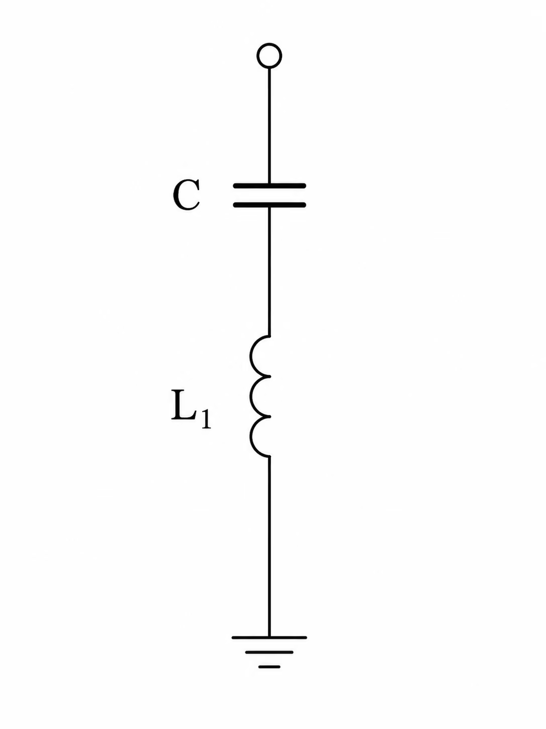
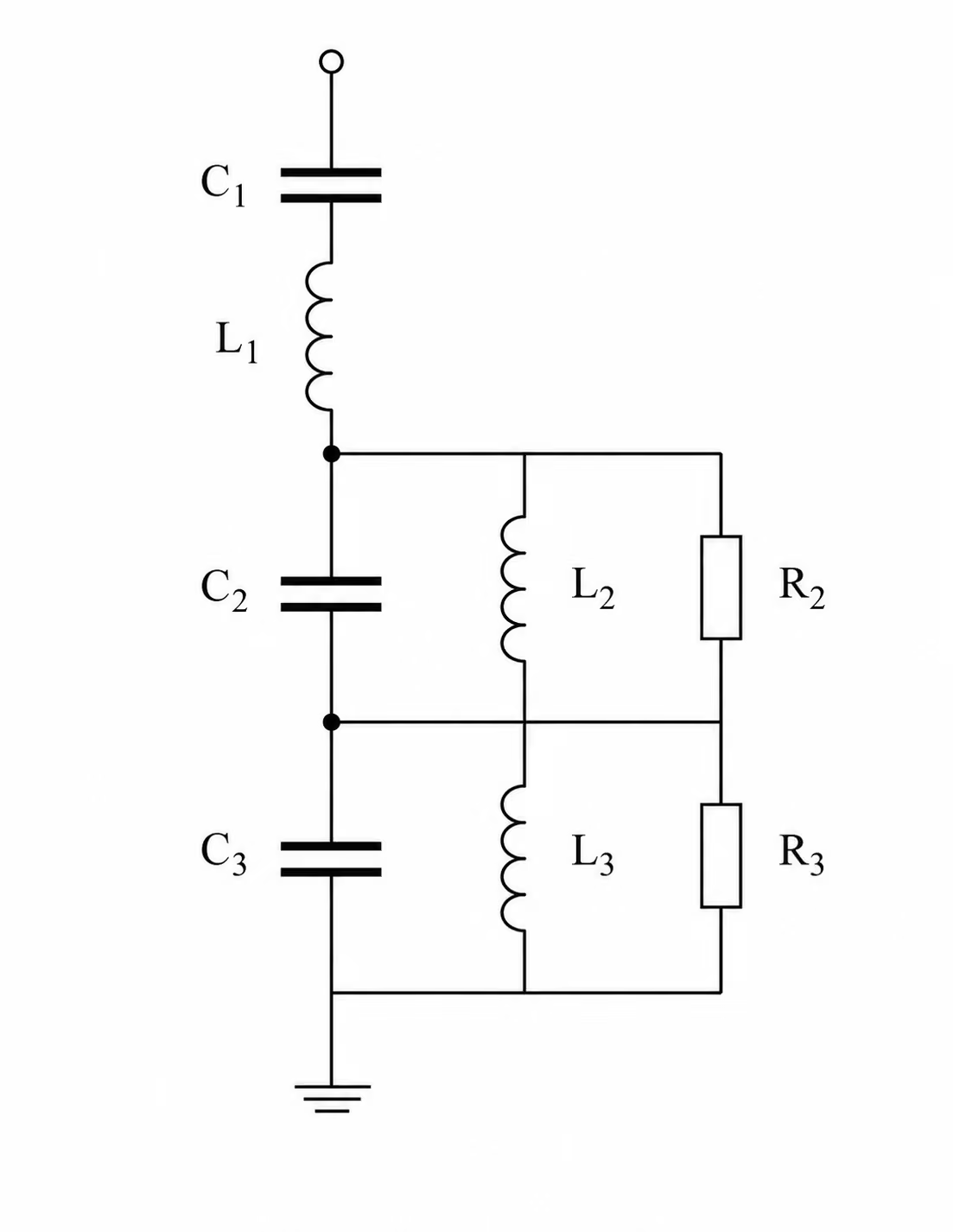
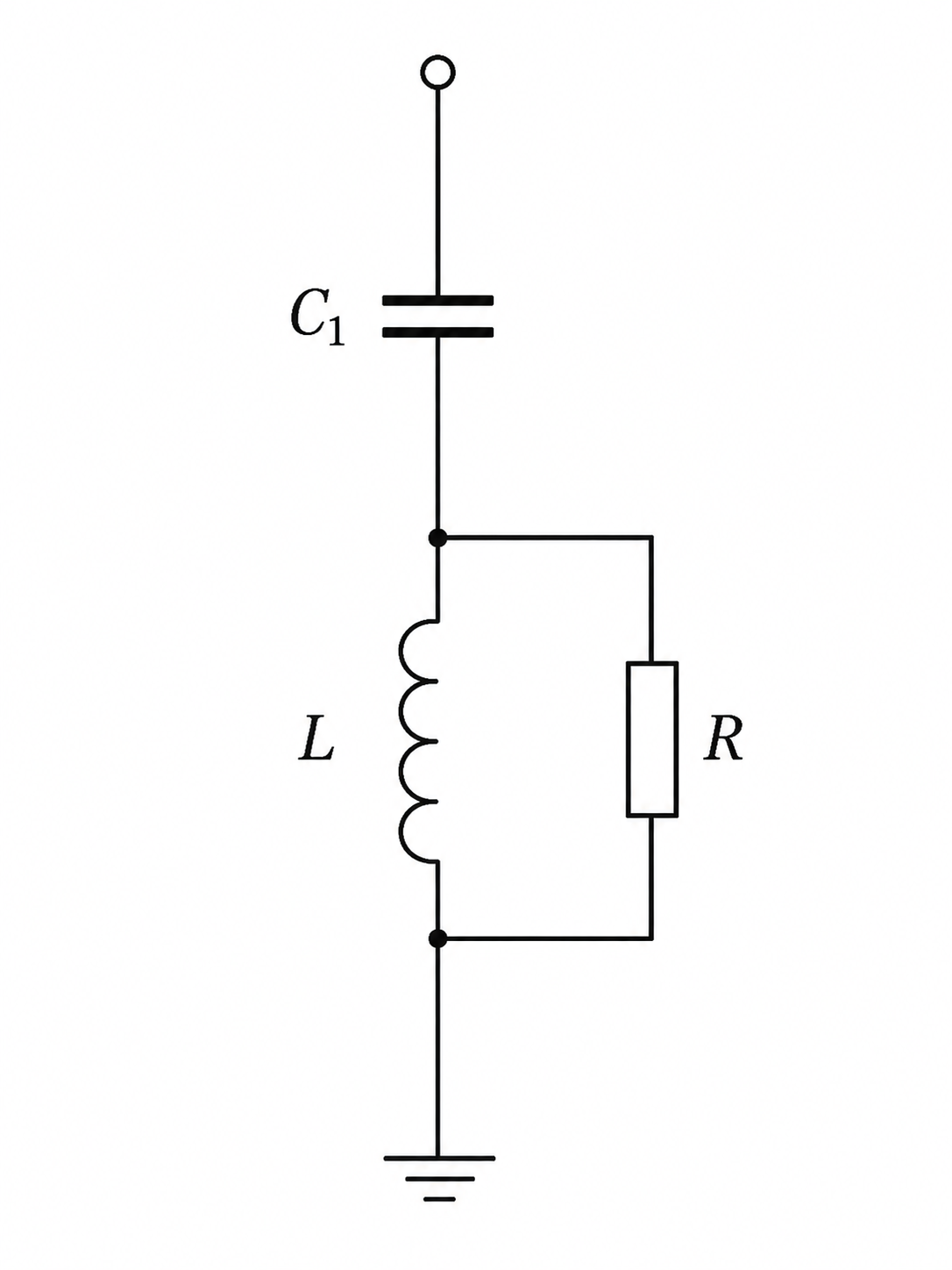
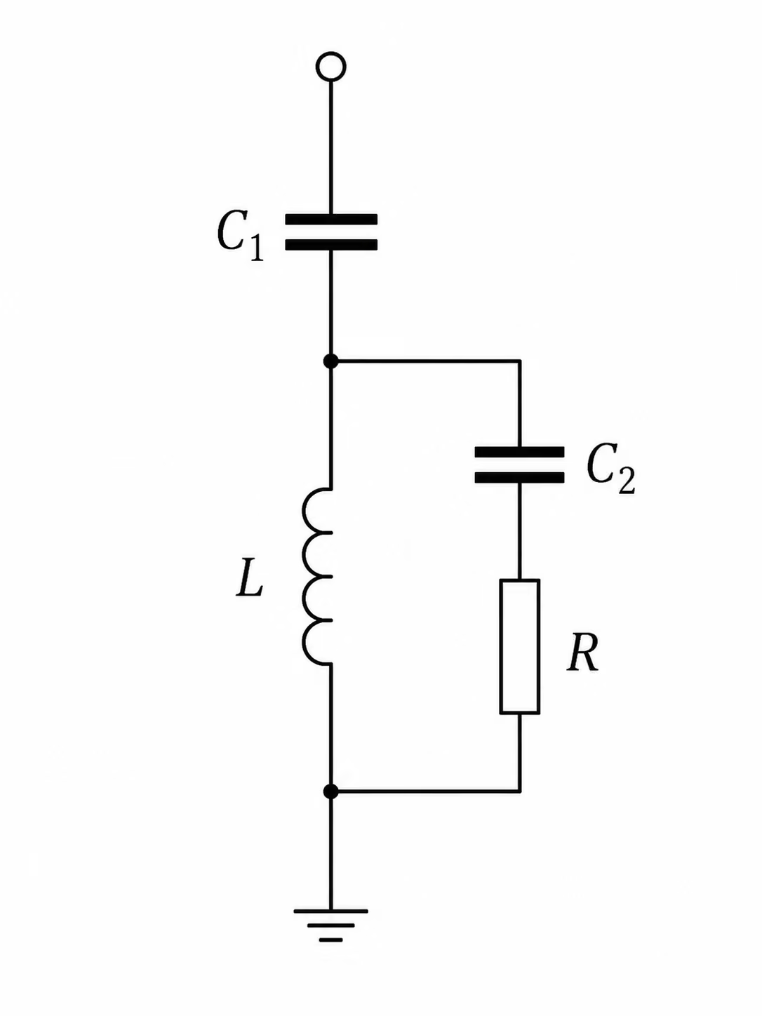
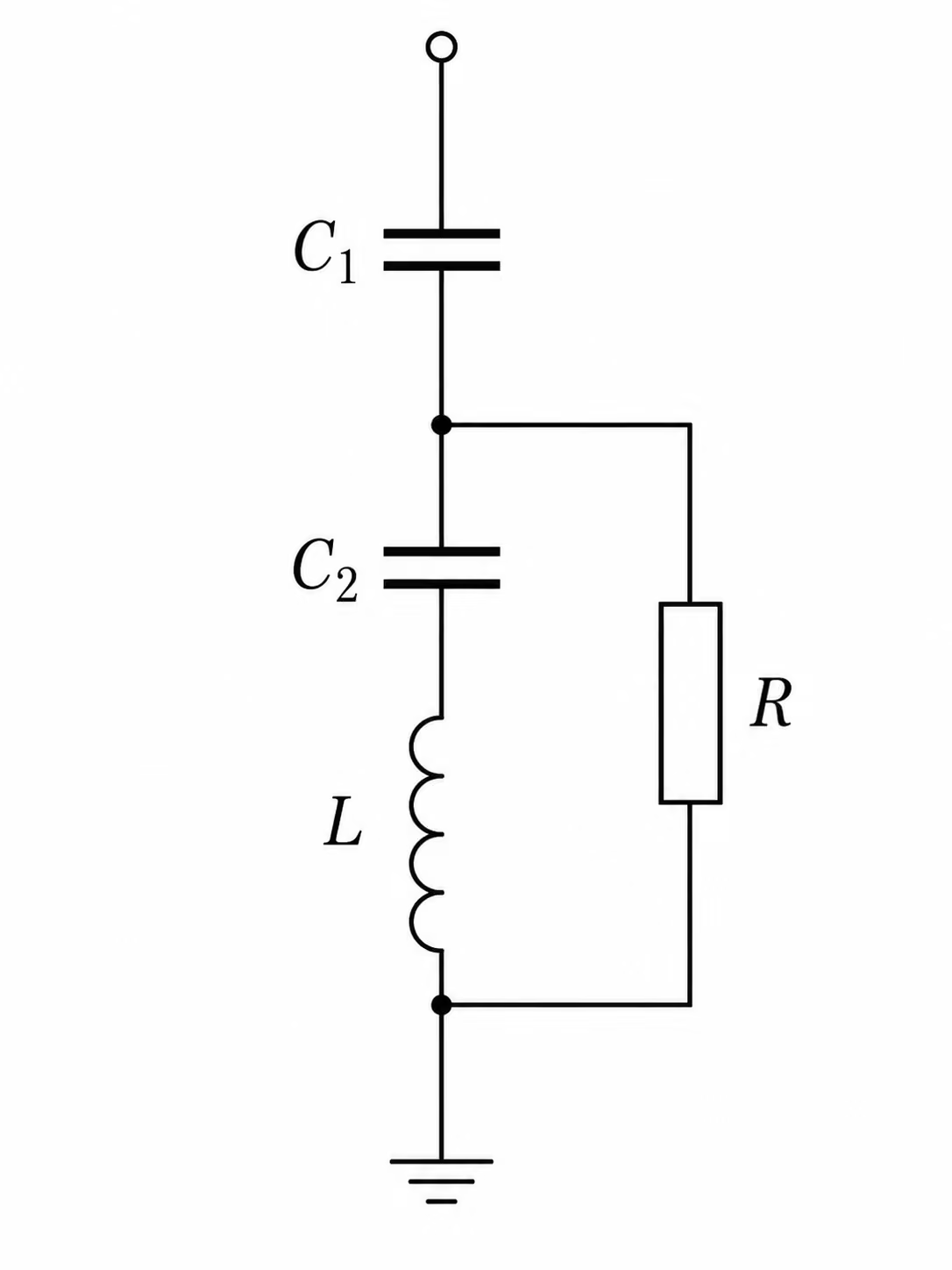
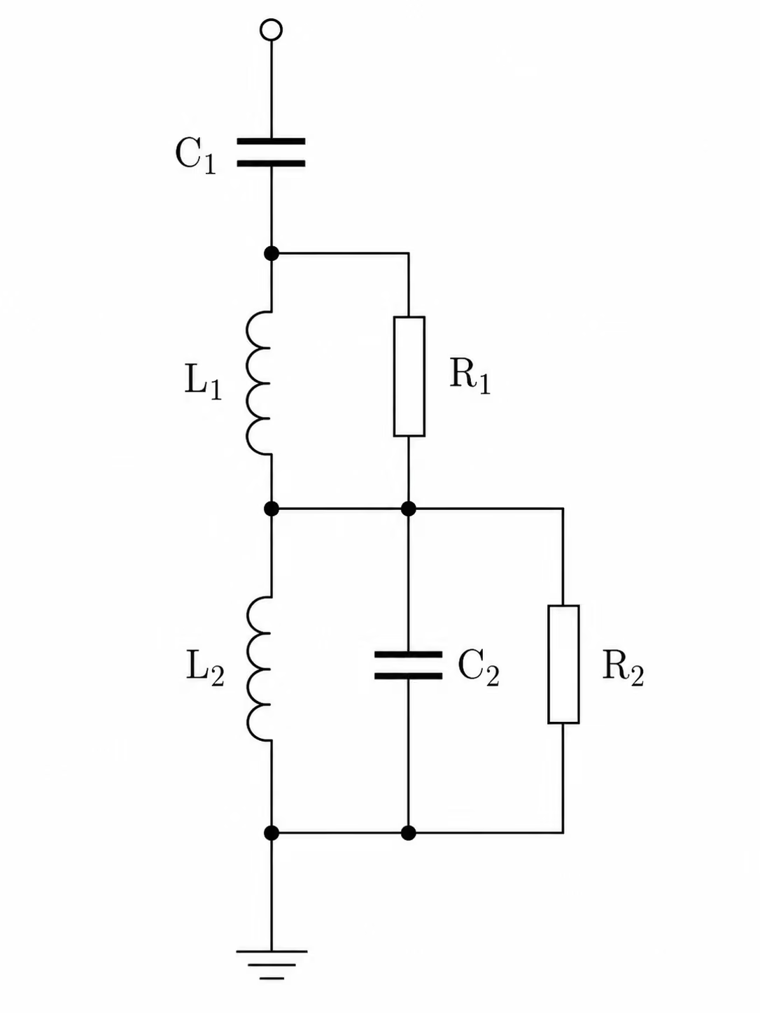
Passive AC harmonic filters are used to reduce harmonic distortion in power systems by providing a low-impedance path for selected harmonic currents or by damping harmonic resonance over a wider frequency range.
Although many classical filter arrangements are often discussed in the context of HVDC converter stations, the same passive filter principles are also used in many AC power-system applications, including:
- industrial plants with large rectifiers or variable-speed drives
- arc furnace installations
- static VAr compensators
- traction and railway supplies
- renewable power plants and collector systems
- MV and LV networks where harmonic distortion or resonance must be controlled
This note focuses on shunt-connected passive filters. These filters are connected from the AC busbar to earth or neutral and are designed to absorb harmonic currents, reduce harmonic voltages, or damp harmonic resonance at the point of connection.
Active and hybrid harmonic filters are not the main focus of this note. They are mentioned later only to clarify the boundary: passive filters are normally preferred where the harmonic spectrum is relatively stable and the required filtering duty is large, while active or hybrid filters may be more suitable where the harmonic spectrum is variable or where interharmonics are important.
The optimum filter arrangement depends on the project. It must be selected based on the harmonic source, the system impedance, the harmonic limits, the reactive power requirement, the available space, losses, component ratings and reliability requirements.
Typical design factors include:
- harmonic current injection limits
- voltage distortion limits
- telephone interference or equivalent interference limits
- system frequency variation
- supply voltage variation
- system harmonic impedance
- negative phase-sequence voltage
- reactive power balance
- permitted voltage step during filter switching
- risk of resonance with the AC network
- available switchgear bays and site area
- environmental conditions such as ambient temperature
- loss evaluation criteria
- availability, reliability and redundancy requirements
For non-HVDC applications, the harmonic limits are normally driven by the applicable grid code, connection agreement or power-quality standard. Typical references may include IEEE 519, IEC 61000-3-6, IEC 61000-2-4 and, in the UK, Engineering Recommendation G5/5. The relevant requirement depends on the country, voltage level, point of connection and type of installation.
Previous projects can provide useful guidance, but they should only be used as a starting point. The final design should always be confirmed by detailed harmonic performance and rating studies.
Simplified filter diagrams normally show only the main capacitor, reactor and resistor components. In practical HV and EHV applications, additional equipment such as surge arresters, current transformers and voltage transformers will also be required.
Surge arresters are often used inside filter arrangements to control insulation levels and protect filter components against transient overvoltages. Their protective level and energy absorption capability should be checked by transient studies.