Power Quality

Passive AC Harmonic Filter Arrangements

Passive AC harmonic filters are used to reduce harmonic distortion in power systems by providing a low-impedance path for selected harmonic currents or by damping harmonic resonance over a wider frequency range.

Reading time ≈ 45 min

Section 1

Overview

Passive AC harmonic filters are used to reduce harmonic distortion in power systems by providing a low-impedance path for selected harmonic currents or by damping harmonic resonance over a wider frequency range.

Although many classical filter arrangements are often discussed in the context of HVDC converter stations, the same passive filter principles are also used in many AC power-system applications, including:

  • industrial plants with large rectifiers or variable-speed drives
  • arc furnace installations
  • static VAr compensators
  • traction and railway supplies
  • renewable power plants and collector systems
  • MV and LV networks where harmonic distortion or resonance must be controlled

This note focuses on shunt-connected passive filters. These filters are connected from the AC busbar to earth or neutral and are designed to absorb harmonic currents, reduce harmonic voltages, or damp harmonic resonance at the point of connection.

Active and hybrid harmonic filters are not the main focus of this note. They are mentioned later only to clarify the boundary: passive filters are normally preferred where the harmonic spectrum is relatively stable and the required filtering duty is large, while active or hybrid filters may be more suitable where the harmonic spectrum is variable or where interharmonics are important.

The optimum filter arrangement depends on the project. It must be selected based on the harmonic source, the system impedance, the harmonic limits, the reactive power requirement, the available space, losses, component ratings and reliability requirements.

Typical design factors include:

  • harmonic current injection limits
  • voltage distortion limits
  • telephone interference or equivalent interference limits
  • system frequency variation
  • supply voltage variation
  • system harmonic impedance
  • negative phase-sequence voltage
  • reactive power balance
  • permitted voltage step during filter switching
  • risk of resonance with the AC network
  • available switchgear bays and site area
  • environmental conditions such as ambient temperature
  • loss evaluation criteria
  • availability, reliability and redundancy requirements

For non-HVDC applications, the harmonic limits are normally driven by the applicable grid code, connection agreement or power-quality standard. Typical references may include IEEE 519, IEC 61000-3-6, IEC 61000-2-4 and, in the UK, Engineering Recommendation G5/5. The relevant requirement depends on the country, voltage level, point of connection and type of installation.

Previous projects can provide useful guidance, but they should only be used as a starting point. The final design should always be confirmed by detailed harmonic performance and rating studies.

Simplified filter diagrams normally show only the main capacitor, reactor and resistor components. In practical HV and EHV applications, additional equipment such as surge arresters, current transformers and voltage transformers will also be required.

Surge arresters are often used inside filter arrangements to control insulation levels and protect filter components against transient overvoltages. Their protective level and energy absorption capability should be checked by transient studies.

Why shunt capacitors cause harmonic resonance

A shunt capacitor does not generate harmonics of its own, but once connected it forms a parallel-resonant tank with the system source inductance. At the resonant order the parallel combination presents a high impedance, so a load-generated harmonic current at that order develops a large voltage and is magnified — the injected harmonic current can even exceed the fundamental — overloading the capacitors and the rest of the plant. Avoiding that coincidence is the main reason a plain compensation bank is converted into a tuned filter.

The resonant harmonic order is fixed by the ratio of the system strength to the bank size:

h = √( kVAsc / kvarc )

where h is the resonant harmonic order, kVAsc is the short-circuit level at the point of application, and kvarc is the bank rating. At a 500 MVA short-circuit level, for example, a bank of roughly 20 Mvar resonates near the 5th harmonic, about 10 Mvar near the 7th, about 4 Mvar near the 11th and about 3 Mvar near the 13th — the smaller the bank, the higher the resonant order.

Crucially, this resonance floats. The short-circuit level is not a fixed quantity: a generator or tie-line out of service, or a block of motor load shed, lowers it and shifts the resonant order, and a later network expansion can create a resonance where none existed. Sizing a bank so its resonant order avoids the load harmonics therefore only holds for one system condition, which is why a frequency scan — injecting a unit current and sweeping the frequency in small steps (typically a couple of hertz, up to a few kHz) to plot the driving-point impedance against frequency — is the standard tool for locating the resonances across the credible switching states. Because a magnified harmonic can drive the bank past its limits, the capacitor standards cap the loading (rms current and kvar each normally not exceeding about 135% of rating, per IEEE Std 18 / 1036); a tuned filter is designed precisely to keep the harmonic within those bounds. For the switching duty of these filter banks — energising inrush, recovery voltage and restrike — see the APS note on switching of harmonic filter banks.

Section 2

General points for passive filter arrangements

Filter earthing

The filter neutral may be:

  • solidly earthed
  • unearthed
  • earthed through a reactor

The earthing arrangement depends on the voltage level, system practice, protection philosophy and local requirements.

For high-voltage applications, the filter neutral is often solidly earthed. For lower-voltage systems, either earthed or unearthed arrangements may be used.

Position of the reactor

In many simplified diagrams, the reactor is shown near the neutral end of the filter branch. In practice, the reactor may be installed either:

  • on the HV side of the filter branch
  • on the neutral side of the filter branch

Each option has consequences.

If the reactor is installed on the HV side, it may be exposed to short-circuit current during an earth fault on the capacitor bank. This means the reactor may need to be rated and type-tested for the calculated short-circuit current, increasing cost.

However, placing the reactor on the HV side can simplify capacitor unbalance protection because the protection equipment can be installed at the neutral terminal.

If the reactor is installed on the neutral side, it is normally not exposed to large short-circuit currents. This can simplify the reactor design and may avoid expensive short-circuit testing.

However, this arrangement may require high-voltage current transformers or voltage transformers for capacitor unbalance protection, which can increase cost.

The reactor position can also affect the transient recovery voltage across circuit breaker contacts when faults are cleared. In some cases, line-side reactors may be avoided because they can create unfavourable circuit breaker TRV conditions.

Section 3

Classification of passive filter types

Passive filters can be classified as:

  • tuned filters
  • damped filters
  • filter order, such as 1st, 2nd or 3rd order
Passive shunt filters Tuned narrow-band harmonic trap Damped broad-band damping Single-tuned Double-tuned Triple-tuned 2nd order (high-pass) 3rd order damped C-type Double-tuned damped
Figure 1 — The two main families of shunt passive harmonic filters and their common arrangements.
Tuned vs. damped: the key distinction

Tuned filters provide a low-impedance path at one or more specific harmonic frequencies using a high Q-factor (narrow, selective response). Damped filters include a resistor that broadens the frequency response, making them less sensitive to detuning but introducing higher losses — particularly in the damping resistor at or near fundamental frequency.

Tuned filters

Tuned filters are designed for one or more specific harmonic frequencies.

They normally have a relatively high quality factor, or Q-factor, which means they have low damping and a sharp frequency response.

A tuned filter provides a low-impedance path at its tuned harmonic frequency.

A tuned filter branch is connected in shunt to the busbar, but internally the capacitor and reactor are selected to create series resonance at the target harmonic frequency. This is an important distinction: the branch is a shunt branch, but the tuning mechanism is series resonance.

Tuned filters are also called narrow band-pass filters.

Examples include:

  • single-tuned filters
  • double-tuned filters
  • triple-tuned filters

A tuned filter is very effective at its tuned frequency. However, because the response is narrow, it is sensitive to detuning caused by:

  • system frequency variation
  • component tolerances
  • ambient temperature variation
  • changes in capacitance or inductance

Damped filters

Damped filters are designed to attenuate a wider range of harmonics.

They include a resistor, normally connected in parallel with the reactor or as part of an auxiliary damping branch. This resistor provides damping and broadens the frequency response.

Damped filters are also called broad band-pass filters.

If the filter is intended to provide attenuation at frequencies above the tuning frequency, it may also be called a high-pass filter.

Examples include:

  • 2nd order damped filters
  • 3rd order damped filters
  • C-type filters
  • double-tuned damped filters

The main advantage of damped filters is that they are less sensitive to detuning and can cover a wider harmonic range.

The main disadvantage is that they usually have higher losses than tuned filters, especially if the damping resistor carries fundamental-frequency current.

Filter order

The expression filter order refers to the order of the terms in the filter transfer function.

In practical terms:

1st order filter

A simple capacitor or RC circuit. This is essentially a shunt capacitor.

2nd order filter

An LC circuit. This may be a single-tuned filter or a 2nd order damped filter.

3rd order filter

A filter with an additional capacitor bank. This may be a double-tuned filter or a 3rd order damped filter.

The filter order is often used to describe the filter type, for example:

  • 2nd order damped high-pass filter
  • 3rd order damped high-pass filter
  • C-type filter

Section 4

Tuned Filters

Single-tuned filter

One capacitor and one series reactor, tuned to one harmonic

A single-tuned filter is the simplest tuned filter arrangement.

It consists of:

  • a capacitor bank
  • a reactor connected in series with the capacitor bank

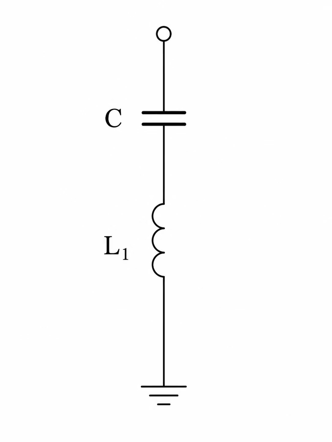
The branch is connected in shunt to the busbar, but the capacitor and reactor are selected so that the branch becomes series-resonant at one specific harmonic order.

At the tuned harmonic frequency, the branch impedance becomes very low. This creates a preferred path for the selected harmonic current.

The impedance at the tuned frequency is limited mainly by the resistance of the reactor.

Single-tuned filter circuit diagram showing a series LC shunt branch
Figure 2 — Single-tuned filter: a series LC shunt branch tuned to one harmonic frequency. At the tuned frequency the branch impedance collapses, providing a preferred low-impedance path for that harmonic current.

Main concept

A single-tuned filter is best when one specific harmonic needs strong attenuation.

For example, one branch may be tuned to one harmonic order, while another branch may be required for another harmonic order.

Because each branch mainly deals with one harmonic, several branches may be required if several harmonics must be controlled.

Tuning and Q-factor

The tuning frequency is determined by the capacitance and inductance values.

The Q-factor controls how sharp the tuning is.

A high Q-factor gives a sharper tuning and stronger attenuation close to the tuned frequency.

A lower Q-factor gives a broader response but less selective attenuation.

The reactor resistance is frequency-dependent, so the reactor design affects the final filter performance.

If an unusually low Q-factor is required, a small series resistor may be added.

Detuning issue

The effectiveness of a single-tuned filter depends on the filter remaining close to its target tuning frequency.

Detuning can occur due to:

  • variation in system frequency
  • manufacturing tolerances in C and L
  • temperature-related variation of capacitance

If the system frequency changes from nominal, the filter will no longer be exactly tuned to the intended harmonic.

If the actual manufactured values of C and L differ from the design values, the tuning frequency also shifts.

This can be corrected by making either C or L adjustable. Since the capacitor bank determines the reactive power output of the filter, it is usually preferable to keep C fixed and adjust L.

This can be done using off-circuit taps on the reactor. However, this increases cost and can reduce reactor reliability.

Advantages
  • simple arrangement
  • only two main components
  • excellent attenuation at one harmonic frequency
  • low losses
  • low maintenance requirements
Disadvantages
  • multiple branches may be needed for different harmonics
  • sensitive to detuning
  • may require off-circuit tap adjustment

Double-tuned filter

Two parallel single-tuned filters combined into one branch

A double-tuned filter is electrically similar to two parallel single-tuned filters, but it is built as one combined filter branch.

It is designed to attenuate two harmonic frequencies.

The total reactive power rating of the combined filter is equivalent to the sum of the two separate tuned filters.

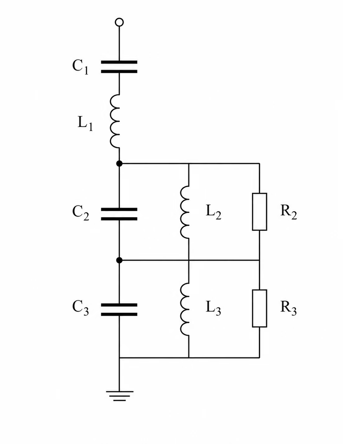
Double-tuned filter circuit diagram with one HV capacitor and one HV reactor serving two harmonic frequencies
Figure 3 — Double-tuned filter: electrically equivalent to two parallel single-tuned branches but implemented as one combined filter, requiring only one HV capacitor and one HV reactor to attenuate two harmonic frequencies.

Main concept

A double-tuned filter provides low impedance at two harmonic frequencies.

Instead of installing two separate single-tuned branches, one combined branch is used.

This reduces the number of high-voltage components and the amount of switchgear.

Mvar split

A double-tuned filter allows flexibility in how the reactive power is shared between the lower and upper tuning frequencies.

This is useful where one harmonic requires only a small filter rating.

A very small separate HV filter branch may be uneconomic or impractical, but it can be incorporated into a larger double-tuned filter.

HV and LV components

A double-tuned filter usually has:

  • one HV capacitor bank
  • one HV reactor
  • additional components operating at lower voltage

This can reduce:

  • site area
  • number of HV switchgear bays
  • HV capacitor protection costs

Reliability and redundancy

Because one branch can attenuate two harmonics, it may be possible to install identical filter branches.

This can simplify:

  • design
  • testing
  • spares
  • maintenance

It can also improve redundancy and overall station reliability.

Detuning issue

Like single-tuned filters, double-tuned filters are sensitive to detuning.

Detuning can be caused by:

  • frequency variation
  • ambient temperature variation
  • component tolerances

Off-circuit tap adjustment may be required to compensate for tolerance effects.

Circulating harmonic currents

The internal C2-L2 circuit can create circulating harmonic currents.

These currents can be high and may exceed the fundamental current in the C2 capacitor.

This can make fusing of the C2 capacitor bank difficult. The current seen by the fuse may be caused by normal internal circulating harmonic current, not necessarily by a real capacitor-element failure. For this reason, some C2 banks may be installed without fuses.

The magnitude of circulating current can be reduced by:

  • lowering the Q-factor of L2
  • increasing the resistance of L2
  • adding a resistor R

The resistor may be connected either:

  • in series with C2
  • in parallel with both C2 and L2

The choice of the two tuning frequencies also affects circulating current. If the two tuned frequencies are further apart, the parallel resonance currents reduce.

Performance between tuning frequencies

A double-tuned filter can give better attenuation between the two tuned frequencies than two separate single-tuned filters with equivalent attenuation at the tuning points.

Transient duty on LV components

During switching or system faults, the transient stress on C2 can be much higher than its steady-state rating.

Therefore, the voltage rating of C2 may need to be higher than the value calculated from steady-state duty alone.

These transient conditions also create extra duty for surge arresters used to grade insulation levels of the low-voltage components.

Advantages
  • optimum attenuation for two harmonics
  • lower losses than two separate single-tuned branches
  • only one HV capacitor and one HV reactor needed to filter two harmonics
  • helps solve minimum filter size problems for low-magnitude harmonics
  • fewer branch types, improving redundancy and spares strategy
  • better attenuation between the two tuned frequencies
Disadvantages
  • sensitive to detuning
  • may require off-circuit tap adjustment
  • transient effects can determine the rating of LV components
  • more complex interconnection with several C, L and R components
  • may require surge arresters to control insulation levels

Triple-tuned filter

Three parallel tuned filters combined into one branch

A triple-tuned filter is electrically equivalent to three parallel tuned filters, but it is built as one combined filter.

It can provide attenuation at three harmonic frequencies.

Triple-tuned filter circuit diagram with one HV capacitor and reactor serving three harmonic frequencies
Figure 4 — Triple-tuned filter: electrically equivalent to three parallel tuned branches combined into one filter, using one HV capacitor and reactor to attenuate three harmonic frequencies simultaneously.

Main concept

A triple-tuned filter can be used to control:

  • three characteristic harmonics
  • or two characteristic harmonics plus one non-characteristic harmonic

The additional tuning frequency may be included to avoid or reduce a resonance problem.

Reactive power control

Triple-tuned filters can help with reactive power control.

This is especially useful when low-load operation is important.

For example, a separate low-order harmonic filter may produce too much reactive power. A combined triple-tuned arrangement can reduce the number of separate filter branches and may reduce the need for additional shunt reactors.

This can be important where reactive power generation must be limited to avoid self-excitation of nearby synchronous machines.

Performance requirements

Triple-tuned filters may be useful where strict interference limits must be met.

They are similar in nature to double-tuned filters, so their advantages and disadvantages are also similar, but with greater circuit complexity.

Advantages
  • optimum attenuation for three harmonics
  • lower losses than three separate single-tuned branches
  • only one HV capacitor and one HV reactor needed to filter three harmonics
  • helps solve minimum filter size issues for low-magnitude harmonics
  • fewer branch types, improving redundancy and spares strategy
  • can help with reactive power control where several harmonics must be filtered
Disadvantages
  • sensitive to detuning
  • may require off-circuit tap adjustment
  • transient effects can determine the rating of LV components
  • complex interconnection with many C, L and R components
  • two or three surge arresters may be required to control insulation levels

Section 5

Damped Filters

Damped filters are used where attenuation is required over a wider harmonic range. The damping resistor broadens the filter response and makes the filter less sensitive to detuning. However, the resistor also increases losses.

2nd order damped filter

Capacitor and reactor with a parallel damping resistor

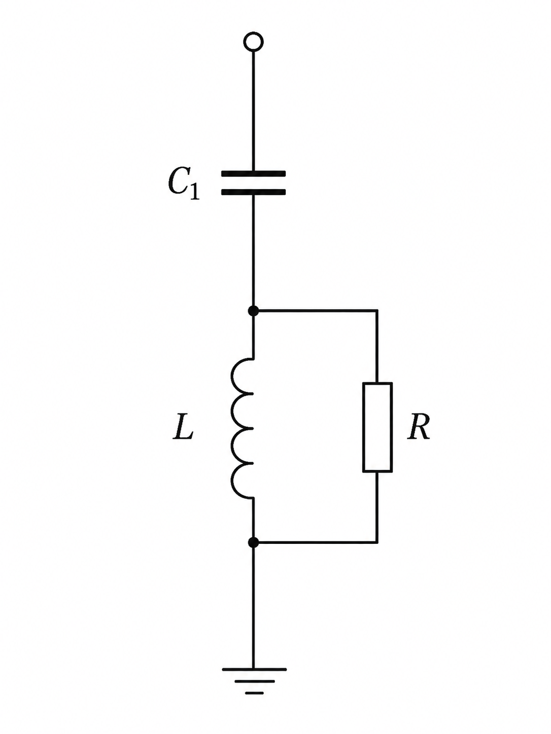
In a 2nd order damped filter, a damping resistor R is connected in parallel with the reactor L.

This gives a wider frequency response compared with a single-tuned filter.

Second-order damped high-pass filter circuit diagram with resistor R in parallel with reactor L
Figure 5 — Second-order damped (high-pass) filter: a damping resistor R is connected in parallel with the reactor L, broadening the frequency response and making the filter less sensitive to detuning compared with a single-tuned branch.

Main concept

The damping resistor makes the filter less sharply tuned.

This has two important effects:

  • the filter becomes less sensitive to detuning
  • the filter can attenuate more than one harmonic

For example, one damped filter can cover a group of neighbouring harmonics more effectively than a narrow single-tuned filter.

At very high frequencies, the filter impedance approaches the resistor value R.

Q-factor and damping

The degree of damping can be described using Q-factor or damping factor.

For this arrangement, the Q-factor definition is different from the Q-factor used for a series-resistance tuned filter.

In both cases, however, Q is a measure of how sharp or broad the tuning is.

A high Q-factor gives a sharper response.

A low Q-factor gives more damping and a wider response.

Performance trade-off

A 2nd order damped filter can cover a wider harmonic spectrum, but its attenuation at one specific harmonic may be weaker than that of separate tuned branches with the same total rating.

Therefore, a larger installed Mvar rating may be required to achieve the same harmonic performance.

The damping resistor also creates losses:

  • at harmonic frequencies, where damping is useful
  • at fundamental frequency, where losses are normally unwanted

These losses can be important if the cost of losses is high.

Advantages
  • attenuation over a wider spectrum of harmonics
  • relatively insensitive to detuning
Disadvantages
  • may require larger installed Mvar rating than multiple tuned branches
  • higher losses than tuned filters

3rd order damped filter

Adds a series capacitor to reduce fundamental-frequency resistor losses

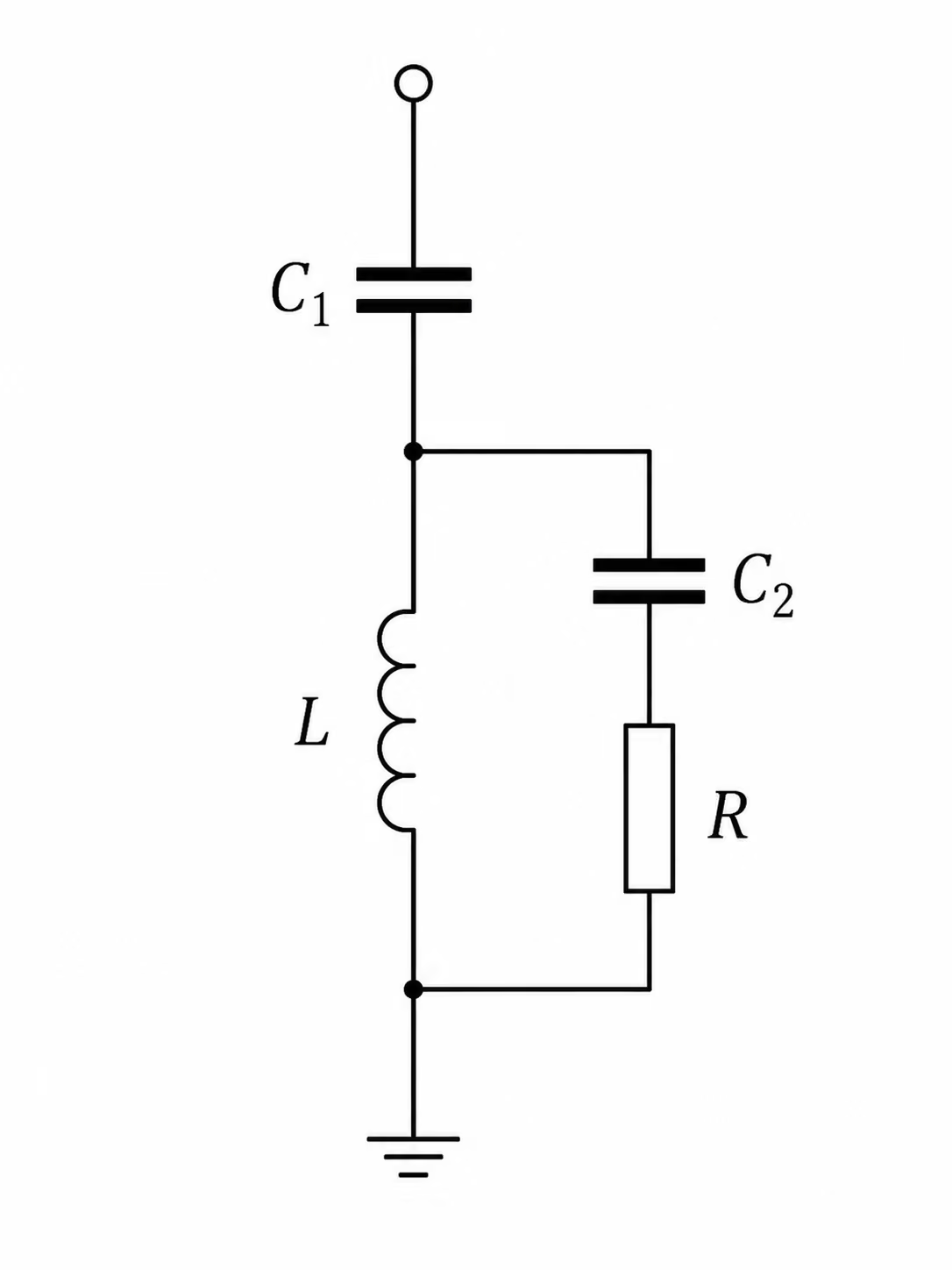
A 3rd order damped filter includes an auxiliary capacitor C2 connected in series with the damping resistor.

The purpose of C2 is to act as a blocking impedance at fundamental frequency.

Third-order damped filter circuit diagram with auxiliary capacitor C2 in series with the damping resistor
Figure 6 — Third-order damped filter: an auxiliary capacitor C2 is connected in series with the damping resistor. C2 acts as a blocking impedance at fundamental frequency, reducing resistor losses while still providing damping at harmonic frequencies.

Main concept

At fundamental frequency, C2 has high impedance.

This reduces the fundamental-frequency current through the damping resistor and therefore reduces resistor losses.

At higher harmonic frequencies, the impedance of C2 decreases.

This allows harmonic current to flow through the damping resistor and provides damping.

Application

This filter is useful at low harmonic orders, where the losses in a 2nd order damped filter resistor would be too high.

Economic trade-off

The selection of C2 is mainly an economic decision.

The benefit of reduced resistor losses and reduced capitalised losses must justify the cost of the C2 capacitor bank.

However, adding C2 slightly degrades the filter admittance characteristic. Therefore, a slightly larger Mvar rating may be needed to maintain the same performance.

Advantages

Same as the 2nd order damped filter, plus:

  • lower fundamental-frequency losses in the damping resistor
Disadvantages

Same as the 2nd order damped filter, plus:

  • slightly poorer performance than the 2nd order damped filter
  • more complex arrangement with additional C, L and R components

C-type filter

Fundamental-frequency bypass for near-zero resistor losses

A C-type filter is a damped filter arrangement designed to provide damping while avoiding significant fundamental-frequency losses in the resistor.

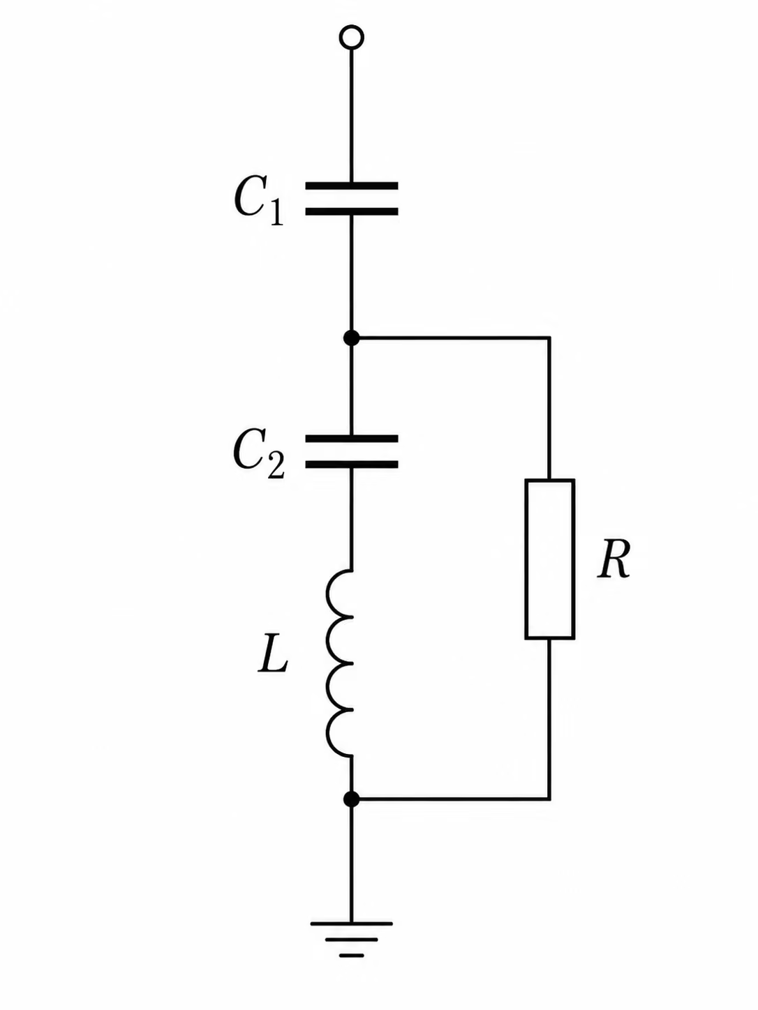
It includes an auxiliary capacitor C2 in series with the reactor L. The C2-L branch is tuned to create a fundamental-frequency bypass for the damping resistor.

C-type filter circuit diagram showing C1, Rd, C2 and L forming a fundamental-frequency bypass around the damping resistor
Figure 7 — C-type filter: C1 is the main capacitor. The series C2–L branch is tuned to the fundamental frequency, providing a low-impedance bypass around the damping resistor Rd at power frequency. At harmonic frequencies the bypass impedance rises and harmonic current flows through Rd, providing damping with negligible fundamental-frequency losses.

Main concept

The C2-L branch is tuned at fundamental frequency.

At fundamental frequency, this branch provides a low-impedance path around the resistor.

Therefore, almost all fundamental current avoids the resistor.

This gives the filter negligible fundamental-frequency loss in the resistor.

At harmonic frequencies above fundamental, harmonic current flows through the damping resistor and provides the required damping.

Key concept: fundamental-frequency bypass

The C2–L branch is tuned to resonate at fundamental frequency. At 50 Hz this branch presents near-zero impedance, diverting almost all fundamental current around the resistor Rd. At harmonic frequencies the bypass impedance rises and harmonic current flows through Rd, providing the required damping. This allows the C-type filter to damp low-order harmonics with negligible resistor losses during normal operation.

Why it is useful

The C-type filter is useful where damping is needed at low harmonic orders but resistor losses at fundamental frequency must be avoided.

For this reason, C-type filters are often preferred for low-order harmonic problems, such as 3rd or 5th harmonic filtering, when a damped response is required.

Detuning issue

The C2-L section is itself a tuned section.

Therefore, it can be affected by variations in L or C values.

In a C-type filter, detuning mainly increases the resistor rating requirement rather than severely degrading the filter performance. This is one reason why the C-type arrangement is attractive for low-order damping applications.

The C2 capacitor also has a small effect on the impedance characteristic.

Advantages

Same as the 2nd order damped filter, plus:

  • negligible fundamental-frequency loss in the resistor
  • useful for low-order damped filtering
  • provides damping without excessive normal-operation resistor losses
Disadvantages

Same as the 2nd order damped filter, plus:

  • resistor rating is sensitive to detuning
  • may require off-circuit tap adjustment
  • more complex arrangement with four C-L-R components
  • slightly poorer performance compared with the 2nd order damped filter

Double-tuned damped filter

Two damped filters combined into one broadband branch

A double-tuned damped filter is electrically equivalent to two parallel 2nd order damped filters, but it is implemented as one combined filter.

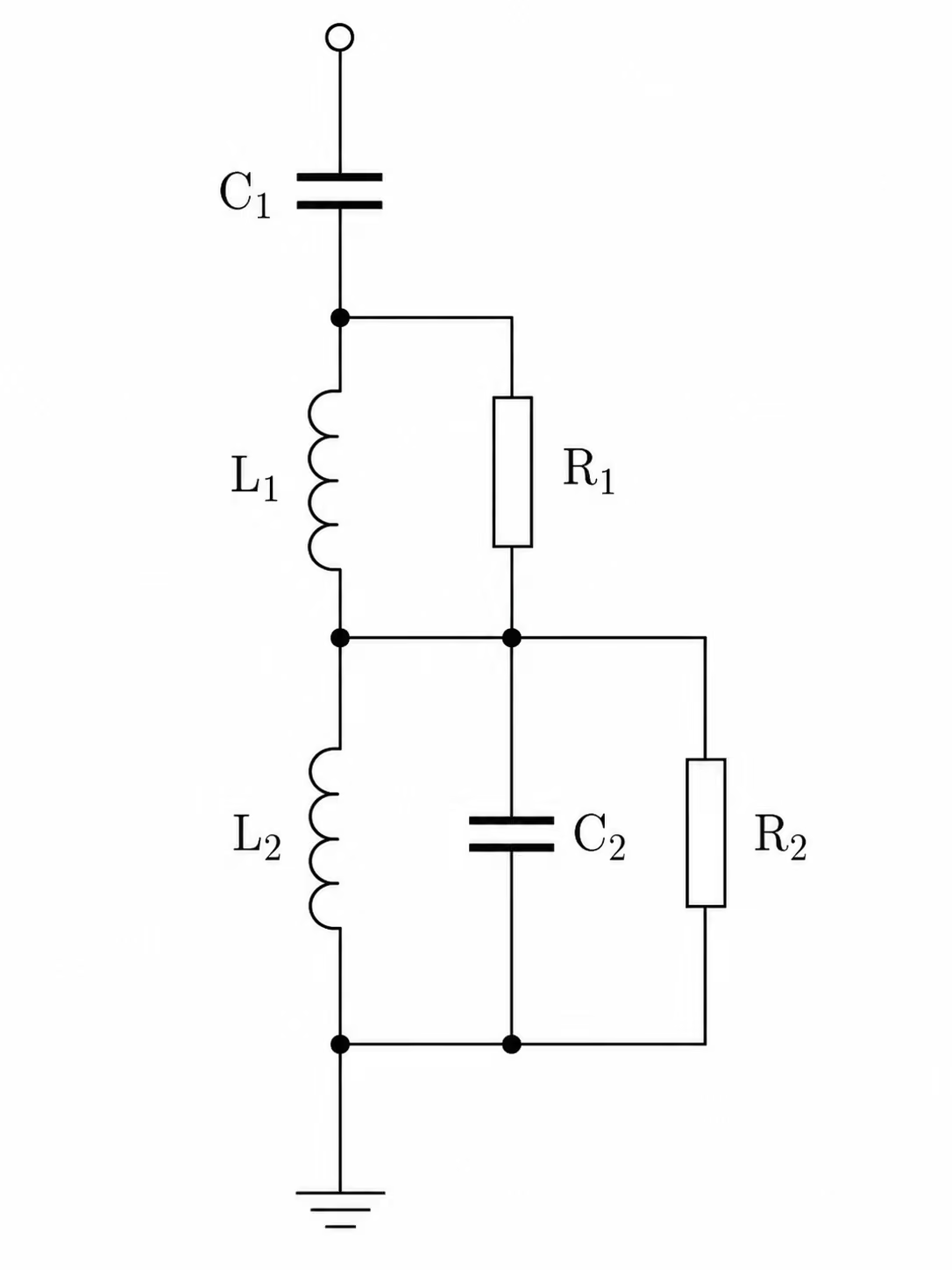
Double-tuned damped filter circuit diagram with resistors R1 and R2 providing broadband damping across two tuning frequencies
Figure 8 — Double-tuned damped filter: electrically equivalent to two parallel second-order damped filters in one combined branch. Resistors R1 and R2 provide broadband damping, making this arrangement less sensitive to detuning than a double-tuned band-pass filter, but with higher losses.

Main concept

This filter provides control over a wide frequency range.

It allows adjustment of:

  • the Mvar split between lower and higher frequency parts
  • the damping level across the harmonic range
  • the shape of the frequency response

It has many of the advantages of a double-tuned filter, but it is less sensitive to detuning because the damping broadens the response.

Losses

The resistors R1 and R2 provide damping, but they also create losses.

These losses occur at both fundamental and harmonic frequencies.

Therefore, a double-tuned damped filter normally has higher losses than a double-tuned band-pass filter.

Transient duty on LV components

During switching or fault disturbances, the loading on low-voltage components such as C2, L2 and R2 can exceed their steady-state overload capability.

Therefore, the rating of these components, especially C2, should be based on transient studies, not only steady-state studies.

Advantages
  • attenuation over a wide spectrum of harmonics
  • only one HV capacitor and reactor needed to filter a range of harmonics
  • helps solve minimum filter size problems for low-magnitude harmonics
  • fewer branch types, improving redundancy
  • relatively insensitive to detuning
Disadvantages
  • transient effects can determine the rating of LV components
  • higher losses than a double-tuned band-pass design
  • complex interconnection with several C, L and R components
  • additional protection requirements for resistors
  • possible additional surge arrester duties compared with tuned filter designs

Section 6

Choice of Passive Filters

The correct filter solution depends on detailed performance and rating studies.

However, the following general guidance can be used.

Frequency variation

If the system frequency varies widely, damped filters are usually preferred because they are less sensitive to detuning.

Ambient temperature variation

If ambient temperature varies widely, tuned filters may suffer performance changes because capacitance varies with temperature.

If off-circuit reactor tap adjustment is provided, the reactors can be re-tuned periodically to compensate for seasonal temperature changes.

Need for close tuning

If filters must be tuned very close to the target harmonic order, off-circuit tap adjustment on the reactors may be required.

Voltage distortion limits

Where the main requirement is to limit voltage distortion, either tuned or damped filters may be suitable.

For neighbouring higher-order harmonics, 2nd order high-pass damped filters can be effective where voltage distortion limits are the main concern and the system harmonic impedance is not severe. A typical example would be a group such as the 11th/13th and above in a 12-pulse converter scheme, but the relevant harmonic orders depend on the actual harmonic source.

Low-order harmonic filtering

For low harmonic orders, such as the 3rd or 5th harmonic, a damped characteristic may be required.

In such cases, C-type filters are often preferred because they provide damping while avoiding high fundamental-frequency losses in the resistor.

Individual harmonic current injection limits

Where individual harmonic current injection limits must be met, tuned or double-tuned filters may be required because they provide a very low impedance path at the selected harmonic frequency.

Telephone interference or equivalent interference limits

Where telephone interference or equivalent interference limits must be met, combinations of damped filters are often required.

Reactive power exchange

Where both interference limitation and reactive power exchange limitation are important, double-tuned or triple-tuned filters may provide the optimum solution.

High-voltage and low-Mvar applications

For high-voltage filters, or filters with low Mvar requirements, double-tuned or triple-tuned filters may be more practical than separate single-tuned branches.

Negative phase-sequence voltage

If negative phase-sequence voltage on the system is high, for example of the order of 1%, 3rd harmonic filters may be required.

These may be either tuned filters or C-type filters.

If C-type filters are used, they may also provide attenuation at the 5th harmonic by suitable choice of resistor value.

In some schemes, control action may also be used to reduce 3rd harmonic generation caused by negative phase-sequence voltage.

Table 1 — Driving requirement versus recommended passive filter arrangement.
Family Driving Requirement Typically Preferred Why
Robustness Wide system frequency variation Damped filters Less sensitive to detuning than tuned filters
Wide ambient temperature variation Tuned with off-circuit reactor taps Capacitance varies with temperature; taps allow seasonal re-tuning
Performance Close tuning to a target harmonic Tuned, with off-circuit taps Taps compensate tolerance and keep the branch on target
Individual harmonic current injection limits Single- or double-tuned Provide a very low-impedance path at the selected harmonic
Voltage distortion limits (neighbouring high orders) 2nd order high-pass damped Effective across a harmonic group where impedance is not severe (e.g. 11th/13th and above)
Low order Low-order harmonics (3rd / 5th) needing damping C-type filters Damping without high fundamental-frequency resistor losses
High negative phase-sequence voltage (≈1%) 3rd harmonic tuned or C-type C-type can also attenuate 5th via resistor choice; control action may reduce 3rd generation
System /
cost
Telephone / equivalent interference limits Combinations of damped filters Broad attenuation across the spectrum
Interference + reactive-power exchange limits Double- or triple-tuned Combine harmonic and reactive-power control efficiently
High voltage and/or low-Mvar requirement Double- or triple-tuned More practical than several small single-tuned HV branches
Key guidance

No single filter type suits all applications. Tuned filters minimise losses and give strong attenuation at a specific harmonic but are sensitive to detuning. Damped and C-type filters tolerate detuning and cover a wider frequency range at the cost of higher losses. Double-tuned and triple-tuned arrangements reduce HV component count and can resolve low-Mvar filter problems. The final selection must always be confirmed by detailed harmonic performance and rating studies based on the specific project conditions.

Section 7

General Application Areas Outside HVDC

Although the original discussion is often associated with HVDC converter stations, these passive filter arrangements are not limited to HVDC.

They are also used in many AC power systems where harmonic currents are generated or where network resonances must be controlled.

Industrial

Industrial plants with rectifiers and drives

Large rectifiers and variable-speed drives can produce significant harmonic currents.

Passive filters may be used to:

  • reduce harmonic current injection
  • reduce voltage distortion
  • provide reactive power compensation
  • avoid resonance with power-factor-correction capacitors

In these applications, the filter may also act as part of the power-factor-correction system.

Furnace

Arc furnace installations

Arc furnaces can produce harmonics, interharmonics and rapid voltage variations.

Passive filters may be used with other compensation equipment to reduce distortion and improve voltage quality.

C-type filters and tuned filters can be useful where low-order harmonic components are important.

SVC

Static VAr compensators

SVCs use thyristor-controlled reactors, which generate characteristic harmonics.

Passive tuned and damped filters are normally part of the SVC installation.

They provide both harmonic filtering and reactive power support.

Traction

Traction and railway supplies

Traction systems can create strong low-order harmonic distortion.

Passive tuned, damped or C-type filters may be used depending on the harmonic spectrum and the system impedance.

Renewables

Renewable power plants and collector systems

Wind and solar plants can interact with collector-system capacitance and grid impedance.

Passive filters may be used where harmonic distortion, resonance or grid-code compliance requires additional filtering.

MV / LV

MV and LV commercial or industrial networks

In MV and LV systems, passive filters may be used for harmonic control and power-factor correction.

However, careful study is required because capacitor banks and filters can interact with the upstream system impedance and create resonance.

Section 8

Passive, Active and Hybrid Filtering — Scope Note

This document focuses on passive harmonic filters. However, in general AC applications, passive filters are not the only possible solution.

Passive filters

Passive filters use capacitors, reactors and resistors.

They are well suited to large, stable and predictable harmonic sources.

They are commonly used where the harmonic orders are known and where the filter can be designed to provide a low-impedance path or damping at those frequencies.

Typical applications include large converter installations, SVCs, industrial rectifiers and high-power installations where passive components are practical and economical.

Passive

Active filters

Active harmonic filters use power-electronic converters to compensate harmonic distortion.

The most common arrangement is the shunt active filter, which measures the harmonic current or voltage and injects an opposing harmonic current in real time.

Active filters are useful when:

  • the harmonic spectrum is variable
  • interharmonics are present
  • the harmonic source changes with operating condition
  • a fixed passive tuned branch would not remain effective over all conditions

They are often used in MV and LV networks, industrial plants, commercial installations and some renewable applications.

The main limitation is rating. The active filter must be rated for the harmonic compensation duty, so it may become expensive at very high power levels.

Active

Hybrid filters

Hybrid filters combine passive and active filtering.

The passive filter handles the main harmonic current or provides the main reactive power support.

The active part provides fine correction, residual harmonic compensation and active damping.

A common reason for using a hybrid arrangement is that a passive filter can interact with the grid impedance and create a resonance. The active stage can then be used to damp this passive-filter/grid resonance and improve the overall response.

Hybrid filters can therefore be a practical compromise where a fully active solution would be too expensive and a purely passive solution would not be flexible enough.

Hybrid

Section 9

Overall conclusion

Overall conclusion
  1. Passive harmonic filters are selected based on the harmonic problem, the network impedance and the project requirements.
  2. Single-tuned filters are simple, low-loss and very effective for one harmonic, but they are sensitive to detuning and may require several branches.
  3. Double-tuned and triple-tuned filters can control several harmonics using fewer HV components. They can reduce site area, improve redundancy and help with low-Mvar filter requirements, but they are more complex and their low-voltage components may be governed by transient duty.
  4. Damped filters are less sensitive to detuning and can attenuate a wider frequency range, but they usually have higher losses.
  5. C-type filters are useful when low-order harmonic damping is needed without high fundamental-frequency losses in the resistor.
  6. Double-tuned damped filters provide wide-spectrum attenuation and good detuning tolerance, but they are complex and have higher losses.
  7. For general AC applications, active and hybrid filters should also be recognised as possible alternatives. Passive filters are strong where the harmonic spectrum is stable and the duty is large. Active filters are stronger where the harmonic spectrum is variable. Hybrid filters combine the high-power capability of passive filters with the flexibility of active control.
  8. The final filter solution must consider harmonic performance, reactive power balance, system impedance, frequency variation, temperature variation, losses, site area, reliability, protection requirements, transient stresses and the applicable harmonic compliance requirements.

Four-Part Technical Series

Harmonic Filters

A four-part guide to harmonic filters — passive filter arrangements, single-tuned filter design, the second-order damped filter, and the active harmonic filter for adaptive current compensation.

Part One Reading now

Passive AC Harmonic Filter Arrangements

How passive shunt filters reduce distortion — single-tuned, double-tuned, high-pass, C-type and detuned arrangements — and where each is used.

Series progress 1 of 4