Power System Fundamentals · Technical Guide

Mitigation of
Resonant Temporary Overvoltages Methods to limit overvoltage magnitude and duration

Reading time ≈ 20 min

Section 7.1

Introduction

Mitigation is required when there is a risk of excessive temporary overvoltages with harmonic content.

Different mitigation methods can be used. Some methods are suitable for general power-frequency TOVs, while others are mainly useful when the TOV contains harmonic components.

The mitigation method should match the cause of the TOV. For example, some methods mainly reduce transformer inrush during energisation, while others change the network resonance and can also help during fault-clearing conditions.

The main aim of mitigation is to reduce one or more of the following:

  • transformer inrush current
  • harmonic current injected into the network
  • network impedance at the critical harmonic frequency
  • duration of the overvoltage
  • energy absorbed by surge arresters and other equipment

Surge-arrester energy duty is an important check in resonant TOV studies because the overvoltage may last long enough to create high accumulated energy stress.

In practice, more than one mitigation method may be used together. For example, operational voltage reduction may be combined with controlled switching.

Section 7.2

Mitigation by operational constraints

Operational constraints mean that grid operators follow defined procedures before energising a transformer. These procedures are intended to reduce the risk or severity of resonant TOVs.

There are two main types:

  • pre-emptive constraints
  • grid reconfiguration

Pre-emptive constraints

Pre-emptive constraints reduce the TOV but may not completely prevent it. The main idea is to reduce the busbar voltage before transformer energisation and/or reduce the transformer inrush current.

If the voltage before energisation is lower, the transformer inrush current will usually be lower. As a result, the harmonic current injected into the network is lower, and the resulting TOV is reduced.

The busbar voltage can be reduced using normal voltage-control equipment, such as:

  • shunt reactors
  • synchronous compensators
  • transformer tap changers

However, the voltage must not be reduced below the allowed operating range of the system. If the voltage is reduced too much, it may affect normal operation and the ability of the grid to respond to unexpected events such as faults.

Using transformer tap changers

If the transformer has a tap changer, the tap position can be selected before energisation to reduce inrush current. The preferred tap position is the one that gives the maximum number of windings on the energised side.

This helps in two ways:

  • it reduces the volts per turn applied to the transformer core
  • it increases the impedance seen during energisation

Both effects reduce the risk of deep saturation and reduce the inrush current.

The tap position must be selected carefully. If the wrong tap position is used and the number of effective windings is reduced, the volts per turn becomes higher and the impedance becomes lower. This can make the core saturate harder and can increase the TOV.

Grid reconfiguration

Grid reconfiguration means changing the network configuration before energisation. The aim is to move the network resonance away from the harmonic frequencies produced by transformer inrush current.

If a certain network configuration creates a resonance close to an integer harmonic, another configuration may shift the resonance to a safer frequency. This can reduce the risk of resonant TOV during transformer energisation.

Main outcome

Operational constraints can be effective, but they depend strongly on clear procedures. Operators must know exactly which steps to take, when to take them, and in what order they should be applied. Without clear procedures, this method is difficult to apply reliably.

Section 7.3

Mitigation by controlled switching of transformers

Controlled switching is used to reduce transformer inrush current during energisation. The main idea is to close the circuit breaker at the best point on the voltage waveform.

The aim is to reduce the difference between:

  • the remanent flux already present in the transformer core
  • the new flux imposed by the system voltage after energisation

If this difference is small, the transformer core is less likely to enter deep saturation. Therefore, the inrush current is reduced.

Remanent flux

Remanent flux can be handled in two ways:

  • by controlled opening, so the remaining flux is predictable
  • by estimating the remanent flux from voltage measurements during de-energisation

Controlled switching can also be used when the remanent flux is unknown. In that case, it may not eliminate inrush current completely, but it can still reduce it compared with the worst case.

Limitations

Controlled switching is not perfect. The ideal closing instant depends on:

  • transformer connection
  • transformer design
  • transformer construction
  • circuit breaker closing-time scatter

Because real breakers do not always close exactly at the target time, some inrush current may remain.

Main outcome

Controlled switching reduces transformer inrush current and therefore reduces the risk of resonant TOVs during transformer energisation. It is mainly applicable to scheduled transformer energisation.

Section 7.4

Mitigation by pre-insertion resistors

A pre-insertion resistor is connected in series with the transformer during the first short period of energisation. The resistor limits the inrush current drawn from the network. After a short insertion time, the resistor is bypassed and the transformer remains connected normally.

Main principle

The sequence is:

breaker closes through resistor → inrush current is reduced → resistor is bypassed

By reducing the inrush current, the harmonic current injected into the network is also reduced. This lowers the risk of exciting a harmonic resonance.

Design requirements

The resistor value and insertion time must be selected by detailed analysis. They must be suitable for limiting the inrush current and reducing the TOV.

In some cases, another issue may control the design, not only the TOV. For example, the resistor may also be selected to reduce current zero-missing. Current zero-missing occurs when the DC component of the energisation current prevents the current waveform from crossing zero, which can be important for breaker interruption.

Limitation

Pre-insertion resistors are effective only for scheduled transformer energisation. They do not solve fault-clearing TOVs, because during fault clearing the transformer breaker is already closed and the resistor is bypassed.

Main outcome

Pre-insertion resistors can reduce resonant TOVs during transformer energisation, but they are not effective for TOVs caused by fault clearing.

Section 7.5

Mitigation by C-type harmonic filters

A C-type harmonic filter can be used to reduce the network impedance at the critical harmonic frequency. This is important because resonant TOVs become severe when harmonic current meets high network impedance. By lowering the impedance at the critical frequency, the filter reduces the harmonic voltage.

Main principle

The filter changes the harmonic impedance of the network. At the tuning frequency, the impedance is reduced. This weakens the resonance and reduces the TOV.

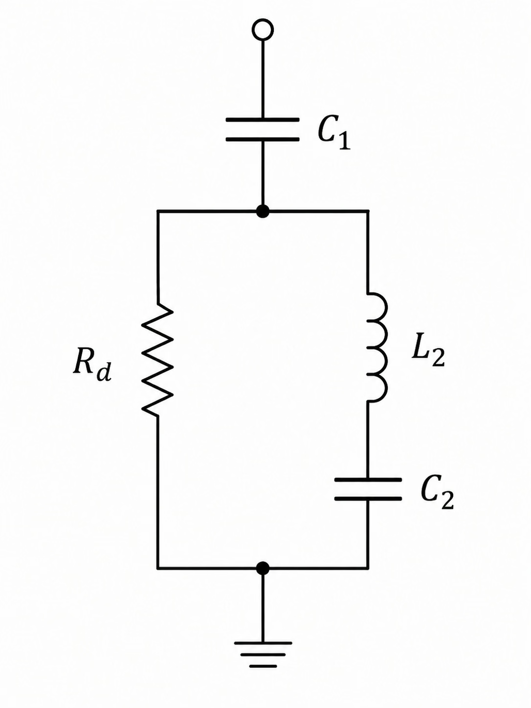
C-type filters are suitable for low-order harmonics, especially the 2nd and 3rd harmonics, because they can provide damping at harmonic frequencies while keeping low losses at power frequency. The reason is that the C2 and L2 branch is tuned to the fundamental frequency. This branch bypasses the damping resistor at power frequency, so the resistor does not dissipate significant power during normal operation.

Main components

A C-type filter includes:

  • main capacitor C1
  • capacitor C2
  • reactor L2
  • damping resistor Rd

The filter parameters define: reactive power rating, tuning frequency, damping performance, and harmonic impedance characteristic.

C-type harmonic filter shunt branch circuit diagram showing C1, Rd, L2 and C2
Figure 1 — C-type filter shunt branch: C1 is the main capacitor of the filter. Rd provides harmonic damping. L2 in series with C2 is tuned to resonate at the fundamental frequency, thereby bypassing Rd at 50 Hz so that no significant fundamental-frequency losses occur during normal operation.

Effect on TOVs

A properly designed C-type filter can:

  • reduce the resonance peak
  • reduce TOV magnitude
  • reduce TOV duration
  • reduce stress on equipment

However, the result depends strongly on the filter parameters. The tuning frequency, MVAr rating, and damping resistance must be selected carefully using detailed EMT analysis.

Important design issues

Filter resistor losses. During harmonic TOV conditions, the filter can carry significant harmonic current. This can cause high energy dissipation in the damping resistor. The resistor must therefore be designed for the expected thermal stress during TOV conditions, not only for normal steady-state harmonic losses.

Surge arrester energy. If surge arresters are used inside the filter arrangement, their energy duty must be checked. These arresters may be installed to protect filter components, for example across the reactor or the C2 branch, against transient overvoltages. During TOV conditions, the arrester may absorb high energy. This energy may exceed the arrester capability if it is not properly selected. EMT simulations are needed to calculate harmonic currents, resistor energy, arrester energy, and voltage stress on filter components.

Filter footprint. A C-type filter requires physical space in the substation. It includes capacitors, reactors, and resistors. At high voltage levels, the reactor size can become a major design constraint. Lower tuning frequencies usually require higher inductance, which can increase the physical size of the reactor.

Reactive power compensation. Under normal operation, the C-type filter behaves like a capacitor bank. This means it injects reactive power into the system. This reactive power may need to be compensated, for example by using shunt reactors.

Main outcome

C-type filters can be effective for both energisation and fault-clearing conditions because they directly modify the network harmonic impedance. However, they require careful design, substation space, reactive power consideration, and detailed EMT verification.

Section 7.6

Mitigation by temporary detuning of system resonances

Temporary detuning means changing the system configuration when a resonant overvoltage is detected. One proposed method is to disconnect selected cable circuits to shift the resonance frequency.

Main principle

The method works as follows:

  • the voltage is measured
  • important harmonic components are extracted
  • if the harmonic voltage exceeds a threshold for a certain time, selected cables are disconnected
  • the cable disconnection shifts the resonance frequency
  • the duration of the resonant TOV is reduced
  • after the inrush current decays, the cables can be reconnected

This method does not necessarily reduce the first voltage peak. Its main benefit is to reduce the duration of the TOV. Reducing the duration reduces the energy absorbed by surge arresters and other equipment.

Applicability

This method is only possible if there are cable circuits that can be disconnected and if disconnecting them has enough effect on the resonance frequency. It is more suitable for networks with parallel cable circuits and separate breakers. It may not be suitable for systems where there is only one cable circuit, or where disconnecting a cable would create operational problems.

System checks

Before applying this method, studies must check:

  • whether the resonance shifts enough
  • whether other components become overloaded
  • whether system stability is affected
  • whether reactive compensation is affected
  • whether new resonances are created
Main outcome

Temporary detuning can reduce the duration of resonant TOVs and reduce surge arrester energy duty. However, it is limited to suitable network configurations and requires detailed screening studies. It is also less mature than methods such as operational constraints, controlled switching, and pre-insertion resistors.

Section 7.7

Mitigation by undervoltage protection

Fault clearing can be a severe cause of harmonic resonance TOV. During a fault, the voltage at the point of interest may collapse. When the fault clears, the voltage recovers suddenly. This can cause virtual re-energisation of transformers and produce high inrush currents.

Undervoltage protection can reduce this risk.

Main principle

If the voltage at the point of interest drops below a defined limit, selected transformer circuit breakers are tripped. This prevents several transformers from being re-energised at the same time after fault clearing. By avoiding simultaneous transformer pseudo-inrush, the risk of resonant TOV is reduced.

Study requirements

Detailed studies are needed to define:

  • the undervoltage level that leads to unacceptable TOVs
  • which transformers should be disconnected
  • how to avoid unnecessary load disconnection
  • whether later energisation of the disconnected transformers could create another TOV risk

Fault distance effect

A fault close to the point of interest causes a deeper voltage sag. A deeper voltage sag causes stronger voltage recovery after clearing. This can produce higher transformer inrush currents and higher TOVs.

A fault further away causes a smaller voltage sag, so the recovery is less severe and the TOV may not be excited.

Main outcome

Undervoltage protection can prevent excessive TOVs by disconnecting selected transformers before severe voltage recovery occurs. However, its application requires careful setting and coordination.

Section 7.8

Sacrificial arresters

Sacrificial arresters are another possible mitigation method. The idea is to use arresters to limit the overvoltage and protect important equipment.

However, this method may only be suitable for certain network arrangements, such as protecting a single transformer. The main concern is energy duty. If the same overvoltage condition happens repeatedly, the arrester may absorb high cumulative energy. This can exceed the arrester capability and lead to failure.

In systems with several transformers close to each other, sacrificial arresters may create further problems because repeated fault clearing or repeated energisation attempts can occur.

Main outcome

Sacrificial arresters can be useful in limited cases, but they are not a general solution for complex networks with multiple transformers.

Section 7.9

Summary of mitigation methods

Different mitigation methods have different applications. The table below summarises each method.

Operational constraints

Applicable mainly to transformer energisation. They are mature and practical, but they do not directly solve fault-clearing TOVs. Their success depends on clear operator procedures.

Controlled switching

Applicable mainly to transformer energisation. It reduces inrush current by selecting the best breaker closing instant. It is mature, but it does not directly solve fault-clearing TOVs.

Pre-insertion resistors

Applicable mainly to transformer energisation. They reduce inrush current by inserting a resistor during energisation. They are mature, but they are not effective for fault clearing because the resistor is bypassed during normal operation.

C-type harmonic filters

Applicable to both energisation and fault-clearing conditions. They reduce the network impedance at the critical harmonic frequency. They can be effective, but they require substation space, reactive power consideration, and detailed design.

Temporary detuning by cable switching

Applicable to energisation and fault-clearing conditions if suitable cable circuits are available. It reduces TOV duration by shifting the system resonance. It has no impact during normal operation, but it is limited to certain network configurations and has limited operational experience.

Undervoltage protection

Applicable when voltage collapse and recovery may cause transformer pseudo-inrush. It can reduce the risk of TOV by disconnecting selected transformers. It requires careful studies and protection coordination.

Sacrificial arresters

Applicable in some energisation and fault-clearing cases. They may be useful for limited configurations but can create problems in systems with several transformers.

Overall conclusion
  1. There is no single mitigation method suitable for all resonant TOV problems. The correct solution must be selected based on the event type, network configuration, resonance frequency, and equipment stress.
  2. Methods that reduce transformer inrush current — such as operational constraints, controlled switching, and pre-insertion resistors — are mainly useful for scheduled transformer energisation.
  3. Methods that modify the network resonance — such as C-type filters or temporary cable switching — can also help under fault-clearing conditions.
  4. Undervoltage protection can help when fault clearing causes severe voltage recovery and transformer pseudo-inrush.
  5. Sacrificial arresters may be useful only in limited cases where their energy duty is acceptable.
  6. In many practical cases, mitigation methods may need to be combined. Operational voltage reduction may be used together with controlled switching, or a C-type filter may be combined with undervoltage protection.
Technical Documents

Simple technical notes for power system studies

The APS Technical Library contains short technical texts written in simple language across different engineering topics. It includes clear notes on power system studies, testing and commissioning, overvoltages, resonance, insulation coordination, grid connection studies, site testing, measurements and practical engineering subjects. The aim is to explain technical ideas step by step, so they can be used more easily in studies, reports, design reviews and technical discussions.